Robert Hart
-
Posts
378 -
Joined
-
Last visited
Everything posted by Robert Hart
-
Any new developments with the FilmFabriek HDS+?
Robert Hart replied to Daniel D. Teoli Jr.'s topic in Post Production
Dan Baxter. The machine is the later version with all rollers being the same. For an immersion version and for a version using a wetting pad, I had been contemplating feeding the film around an inner roller first, over and out to the outer roller, up and around that then into an immersion tank/gate. That would achieve an entry and exit of the film higher than the gate area which could become a fluid reservoir. The film would travel under, not over the guide pins. The light pin would need to be relocated. -
Any new developments with the FilmFabriek HDS+?
Robert Hart replied to Daniel D. Teoli Jr.'s topic in Post Production
I lurk and hope to pick up a bit of knowledge along the way. Meanwhile, thanks to a few folk here, in the private messages and on the Resolve forum, I am making some progress on the learning curve. This clip does have some jitters but it is mostly in the actual print from negative done some 40 or more years ago when 16mm film was still the go for news and current affairs. If anyone has invented a wet-gate for the Retroscan Universal Mark II, I am all ears. It could be doable by re-routing the path through the existing rollers, with hollow pillars through the tank for mounting to the existing guide threads and working out a way to project the light pin through the fluid or if the lightpin itself can swim without harm. -
The slow response suggests light fractions have evaporated from the original lube over the years and what remains has become gummy. As a hack you, might glue a thin piece of shim material or plastic about 0.7mm thick (cereal packet cardboard) where the release plunger contacts the inside face of the cover. Another hack you might try would be to get hold of some light mineral thinners like automotive acrylic thinners which will evaporate away before spreading too far inside. Run no more than about ten drops down the channel the plunger slides inside of in the hope that the thinners will migrate to the contact surface and rehabilitate the lube. Do not infuse any more or the governor bell and its special friction pads may become implicated. All bets then will be off. I do not know what that contact surface is. It may be a metal-to-metal friction clutch or some sort of ratchet. If it is a clutch then a risk may be that there is a thin pad of added friction material like felt, leather or rubber. If it is a felt disk, then no harm is likely but the thinners might ruin other materials. I had to take mine apart many years ago when it got water in it from being shipped to me in a freezer truck. The taking apart is not for the faint-hearted. The only thorough option is to have the camera serviced. The rest of the lube in the camera will also be in a poor state.
-
Have you tried manually pushing the counter reset trigger before putting the cover back on?
-
Lens centering: Should the mount move down or up in this case?
Robert Hart replied to Fedor Karpenko's topic in 16mm
You may not detect a tilt with flange to focal plane manual measurement. The distance added or subtracted by a tilted mount or lens tail to produce an off-centred image on a 16mm sized image area would be very small. Some swarf or grit between the mount and the camera body might be all that is needed to cause it. How to find it is a challenge. A test roll with the camera set up with the mount face perfectly at 90 degrees to a focus chart with the chart lit for the lens to be set at wide-open aperture or projection of a texture on a groundglass panel in the gate through the lens may show softness in edges or corners indicating an off-axis tilt. That assumes the centering of the lens mount was done correctly in the first place. With the small 16mm image frame there is not much room for error. What you have there is about a 0.5mm error. The former Soviet K3 may not have been an exemplar of precision and alterations since may not have been either. Another consideration is whether the claw crank mechanism has become worn and the claw has begun to strike short. For a 0.5mm error I would expect a LOT of mechanical noise and clicking of misregistering when the claw engages into or disengages from the sprocket holes in the film. If the option of sending the camera to a tech is not viable, my personal preference would be to selectively loosen but not remove the fastening screws across the lower semi-circle of the mount-to-body attachment. There may be enough compliance in the body for the lens to tilt upwards and carry the optical centre axis upwards slightly. To check this without rolling film through the camera would require making a groundglass focus target to fit into the gate and reverse projection with the camera very firmly mounted to a solid base. Somebody else can correct me here. - An off-axis movement of the lens, either a tilt or simple lateral movement carries the image circle across the focal plane in the same direction as the movement of the lens. If your test restores the image centre, then my personal preference purely as a backyard engineer would be to remove the mount from the body, check the matching faces for swarf and grit, remove the contamination, reassemble and test again. If that does not work, then my next personal preference would be to find the thinnest possible scrap of shim material about 5mm in area and fit it between the mount and body at the lowest point on the lower half-circle of the mount, then refasten all screws. This will tilt the lens axis upwards and raise the centre of the image circle at the focal plane. If this succeeds and you are content with having an uneven loading of the structure then no more needs to be done. It is more likely you will find that the error has become over-corrected. Edge or corner softness may have been introduced. My personal preference if the image remains sharp across its entire area would be to polish the upper half circle of the mount to body contact face on the body with a tightly bunched bud of steel wool, clean, re-assemble and retest to see if there is any difference. Take care to plug the centre hole against loose fragments of steel wool entering and causing trouble. Please take heed of better and smarter people than I if they respond here. There are correct ways of doing this, not my kitchen-table methods. -
Lens centering: Should the mount move down or up in this case?
Robert Hart replied to Fedor Karpenko's topic in 16mm
Before you set about keyholing the attachment screwholes or other surgeries to move the optical centre of that lens mount, it might be worth checking if there are any shims that have folded or creased at the screwholes and tilted the lens off-axis. A practical test for off-axis tilt might be to open the lens iris up to the maximum and look for soft focus on an upper or lower frame edge. You would need to have a flat textured surface or even better, a proper chart as a focus target with the camera set up dead level and square-on to the focus target. -
If you are going DIY with the Angenieux, take care matchmark everything you take off. It is vital to note and mark exactly where in the rotation when unscrewing the front barrel off the focus helicoid that it comes off. To be sure where in the rotation it finally detaches, put one matchmark on the main assembly first, then as you unscrew the front barrel, draw forwards so that when the last thread lets go you will observe exactly when it releases and pulls away forward. That's where you should start the thread when you reassemble. Immediately offer the front barrel back to the main body and make the second matchmark on the front barrel. There can be several starting points with helicoids. They are a mongrel to get started. Getting it wrong, then having to start over several times until you find the correct one can be extremely frustrating.
-
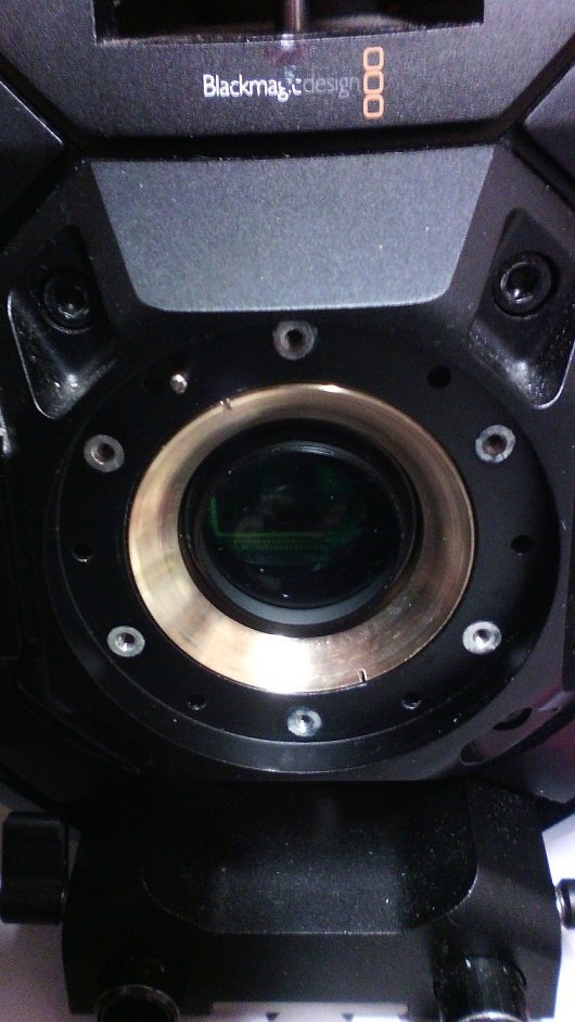
Dom Jaeger. I agree with you that it will not automatically spread within a population of stored lenses so long as that storage as you point out is not favourable to help fungus grow. Some lenses like the big Sigma zooms, physically breath in and out through the back end when the extending zoom barrel moves out and in. Fungus spores are more likely to get inside one and come right on out if an infected lens zoom is operated. A 50-500 I have was a mess. It was also a nightmare to dismantle and clean. I also discovered what the noise and slightly baulky motion was. A slot cam follower had pulled its securing screw loose. So being prompted by the fungus to open the lens up was fortunate in a way.
-
It looks like fungus to me. I was loaned a couple of Cooke (Taylor Hobson) lenses which were fungussed. In an ideal world, infected lenses should be stored separately from known good lens sets. Whilst the fungus is contained within the infected lenses it will migrate to the outside due to expression of air when the focus group moves. Your hands may then move the infection to other lenses. If it has not been left too long, the lenses are recoverable but internal elements may need to be polished and recoated because the fungus will have etched into the coatings. I am not sure whether the old Cookes had anti-reflection coatings on the internal glass, maybe just on the front and rear glass. If you are not sending the lens for repair/service, it may be best to bag it and give your hands a good wash in vinegar then water. That lens is worth keeping and having treated, sooner rather than later. If it is a Cooke, especially Series II, it will still have considerable value, even in that state. Other ARRI Standard/B-Mount lenses are worth saving as well. You can stall the fungus by uncapping the lens and letting direct sunlight fall into it for several days or set up a UV lamp to do the same job. If you are going to throw it out, don't. Please send it to me.
-
It has been suggested that the filmstock itself is manufactured in China. It was mentioned elsewhere that the pre-release stock sent out for stills photographers to test and appraise was installed into cassettes in China. It will be educational to learn the full and correct story. Meanwhile, I am waiting for a chance to try the new 16mm NC500 film in a CP16R camera I have that still works.
-
Any new developments with the FilmFabriek HDS+?
Robert Hart replied to Daniel D. Teoli Jr.'s topic in Post Production
There used to be available platters for cores. With a cover disk added, it will work well enough upright. For tidy rewinds without waves and ripples, my personal preference is to shim the core platter a little forward so that the film is always just brushing the platter surface. -
Future of Cinematography! What’s next?
Robert Hart replied to Saikat Chattopadhyay's topic in General Discussion
The whole affair could collapse into a niche craft sponsoring by small cliques of well-moneyed audiences much like live theatre, opera and symphonic orchestra. John Humble Cit, Joan Humble Cit and the kids may watch extreme low-budget limited-distribution fare when they can afford to take time off from the three jobs to make ends meet. The future may become live interactive alternative reality and gaming but the freedom to indulge in that may also be tied to the future lower discretionary spend of the serfs and time off when other needs to get by can be deferred. -
What is verdict on Cintel 2 scanner for 16mm?
Robert Hart replied to Daniel D. Teoli Jr.'s topic in Post Production
The flicker is consistent with a spring driven camera's centrifugal governor hunting for correct speed while the power of the spring diminishes as it winds down. It is also consistent with a LED flicker artifact introduced by the scanner. However that may be unlikely in a professional level machine. My money would be on the camera's governor. If it is a bell type centrifugal governor, then the friction pads might have become a little sticky if camera lube has crept in. Light fractions in the camera's lube oil might have gassed off over time leaving the remaining lube thicker or even dry. A service by a proper camera tech would not hurt. Those who know all the wrinkles that Bolexes and K3s throw up might be scarce by now. -
A reel-to-reel fulltrack playback head connected to a magnetic amp input yields a satisfactory result with sprocketed magnetic film, not an ideal result for post-production but okay for playbacks. I doubt you can buy them as a trade part these days. I used one to build a home-made editor driven by a GM windscreen wiper motor. If the Restroscan transport could be stabilised by adding an inertia wheel in the path, a fulltrack playback head would probably work fine. It probably would not be too hard a task to add a record/playback head for sound-on-film so long as the correct pins are connected or you might erase your sound track. A module which attached to the existing fixing for the two film guides would not be too hard to build. My original playback head for the home-made editor was mounted on a door hinge for the convenience of swinging it aside from the film path. Agfa sound film is thinner and possible a little more fragile as far as edge guides are concerned.
-
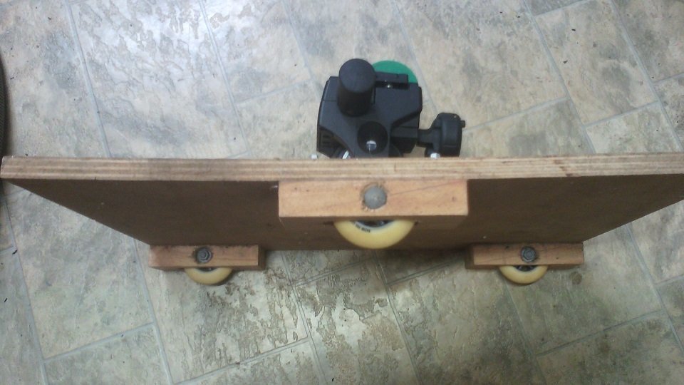
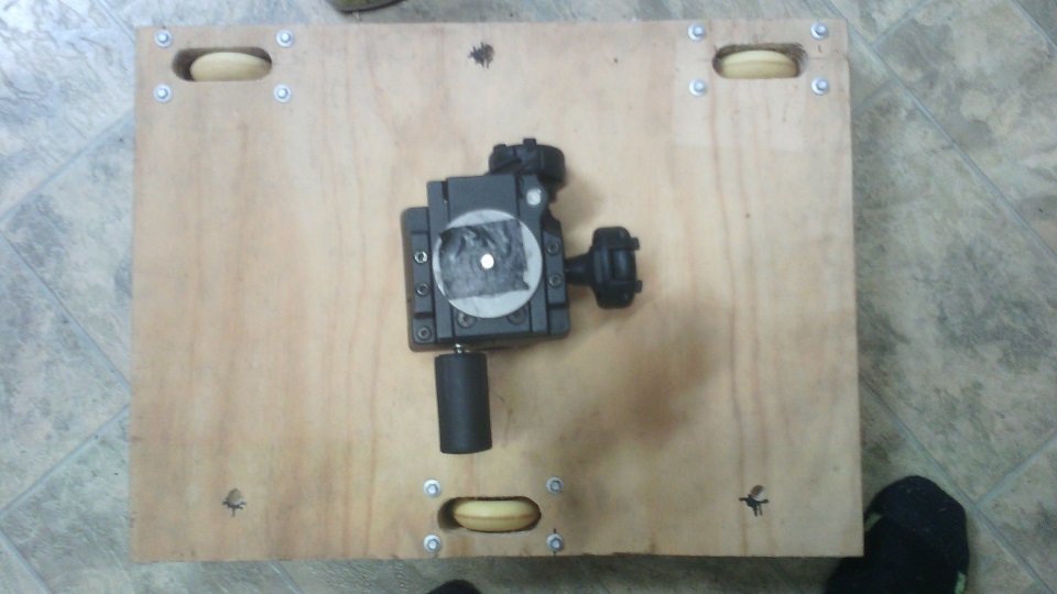
This poor man's ersatz skater is slightly larger than P+S Technik's genuine article. There are also three holes for spiked tripod feet. The wheels are replacement rollerblade wheels. You need to be careful mounting them or your skater will go around bends. This thing is only suitable for prepared surfaces like tabletops, indoor floors or timber basketball courts. If you are a larger rideable skater which is free and not on rails, you will be best served by making a deck with eight wheels in two rows of four so that like a military vehicle, if one wheel goes over a hole, the remaining wheels will keep the deck relatively steady with none of the thump-thump of four wheel arrangements.
-
I wonder if there might be a revival of the sort of minilabs we used to see all over the place in shopping centres and pharmacies as side hustles for small businesses. They are probably most in landfills or recycled by now. Being able to locally process 16mm film would be a bonus if a minilab could be modified to run 16mm film through. The downside of course would become quality control. The chemicals must be maintained. Stills film I had processed in some third-world minilabs was not all that impressive.
-
ALCS Single-Speed Crystal Controller for CP16R
Robert Hart replied to Aapo Lettinen's topic in Cinema Products
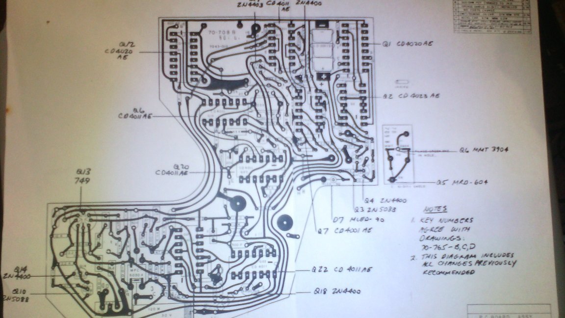
Aapo. Is this the mage you want scanned or is the circuit diagram required? The page is A3. Some of the component valued are covered by the traces. There is a separate parts list.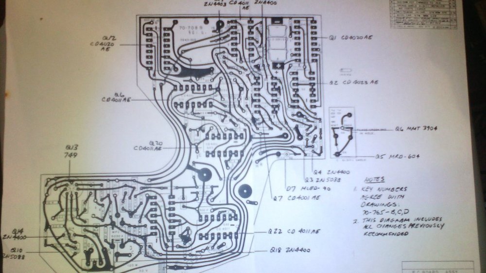
-
Help identifying lens adapter: Arri Standard to ? ...
Robert Hart replied to Sean Cheung's topic in Lenses & Lens Accessories
You might be able to fit a simple ARRI standard to PL-Mount adaptor ring but I suspect that the knurled ring on the front of the adaptor you have illustrated may be wider than the clearance relief machined into the front face of ARRI S/ARRI B to PL-Mount adaptor rings. That knrled section might have to be truned down to the clearance diameter on a lathe. There seem to be Cameflex to PL-Mount adaptors. https://www.ebay.com.au/itm/273975136514 -
Help identifying lens adapter: Arri Standard to ? ...
Robert Hart replied to Sean Cheung's topic in Lenses & Lens Accessories
It looks a little like this one. https://www.ebay.com.au/itm/325256615767?chn=ps&_ul=AU&norover=1&mkevt=1&mkrid=705-139619-5960-0&mkcid=2&mkscid=101&itemid=325256615767&targetid=&device=c&mktype=pla&googleloc=9070517&poi=&campaignid=15791083372&mkgroupid=&rlsatarget=&abcId=9300816&merchantid=510825023&gclid=Cj0KCQjwqoibBhDUARIsAH2OpWiUUTifpR8HyCvE254KH3wh7fAC0KzGnhWV_BJ4oo2gV89RIbm8b4AaAg-wEALw_wcB -
S16 pl to pl focal reducers, and can you shoot in normal 16mm on a 416?
Robert Hart replied to Edith blazek's topic in 16mm
I think the first Lucadapter may have been for the older Ursa Mini 4K so they have been around for a while. These were my speedbooster mods for "big" Ursa 4K with the modified mount removed and the modified IMS-Nikon F-Mount Speedbooster. Luca went one step better and was apparently able to make a workable Ursa Mini Pro version.
-
S16 pl to pl focal reducers, and can you shoot in normal 16mm on a 416?
Robert Hart replied to Edith blazek's topic in 16mm
Phil Rhodes. I assume that your comment "moving the sensor closer to the mount" also suggests using another mount system which is closer to the sensor and has universal adaptors. On the SI2K I was able to modify a speedbooster for Nikon F-Mount for the original Blackmagic Pocket camera to offer into the P+S Technik IMS-Mount, (a universal mount) which is just 0.25mm shy of the M/43 flange to focal plane distance. It was doable "just". It could not be done for the Canon EF-Mount. In the Mini Pro camera family, the ND filter wheel enclosure on front and the IR filter, there might be some problems in redesigning the front lens mount support to be closer to the sensor to enable a universal mount system. BM more or less offers this anyway in the Mini Pro camera family with the choice of mounts to fit on front of the existing lens mount support. Lucadapters offer indwelling speedbooster adaptors for the Mini Pro camera family. I am not sure how Luca got around the infinity focus problem but a thicker planar element replacing the existing IR filter would solve it and I think that is how he got around it. -
S16 pl to pl focal reducers, and can you shoot in normal 16mm on a 416?
Robert Hart replied to Edith blazek's topic in 16mm
There exists no PL-PL focal reducer. There is also not enough workspace between the PL-Mount and the mirror of a reflex 16mm/Super16mm camera for the optics of a focal reducer to fit. How would I know, some might ask. I have installed focal reducers in the SI2K digital cinema camera and the original "big" Ursa digital cinema camera. Even with the deeper available workspace between rear of the lens and the IR filter in these cameras, it was doable - "just". Before affordable focal reducers like the Metabones Speedbooster came along, folk were using groundglass based non-coherent image relay adaptors like the P+S Technik Mini35, Pro35 and the many alternative adaptors which followed. I tried this in a rough and ready arrangement on a CP16R film camera. The image was not outstanding, primarily due to the relay optics being matched for 1/3" video cameras, not the near-to 2/3" image area of the 16mm film. You lose up to one and two thirds of light in conditions requiring wide open lens aperture and there are two focusing systems to contend with. By the time one could cobble up a means of relaying the field-of-view of a 35mm motion picture frame to the 16mm motion picture frame, it would be far cheaper to buy 16mm/Super16mm motion picture camera lenses and a lot less frustration when using them. Over on www.reduser.net there was discussion about a focal reducer which adapted medium format lenses like Mamiya 645 types to RED cameras. What the distance is between the rearmost optical element of that adaptor and the film plane is I have no idea. -
If your aperture was set to f15, (I am assuming the "5" in "15" is a typo and you meant "f16"), then the softening will be due to diffraction. You should aim for a wider aperture in the ballpark of f5.6 by using ND filters or even better, IRND filters. Then I think you will see an improvement. IS0400 may spoil your whites. You might be better off using enough ND to allow you to set your camera's ISO to its sweet setting or even more ND to enable a higher gain setting to protect bright details like clouds in sky and the form of light coloured motor vehicles and the texture of bright walls. Please take more heed of the comments of wiser folk than I who may add comments.
-
BMPCC 4K Anamorphic 1.33x - Drifter Character Intro
Robert Hart replied to Bulent Ozdemir's topic in BlackMagic Design
If your camera has a PL-Mount, then a lens sandwich with a Laowa PL-PL rear-anamorphic adaptor behind your lens and the SLR Magic front anamorphic adaptor will confer a 2x anamorphic squeeze. If you want a more distressed look, a Century Optics 16:9 front anamorphic adaptor might do it for you. You would have to find a version with a filter thread mount on the back, not the bayonet mount Sony version. I made a threaded adaptor for the Sony version. This however limits the lenses you can use to lenses with a closely coupled 52mm or 58mm filter thread fronts like Nikons and about 50mm focal length. Any wider-angle lens will vignette. I have machined a new thread for the back of an Ishico Proskar 2x anamorphic projection lens. Infinity focus requires a small mod to the Ishico lens and manging two interacting focal adjustments is as much the irritating challenge on a camera as it is for projection. -
There are some C-Mount lenses which are a bit awkward for controllability as they tend to come unscrewed. They are branded Fujian and can be found in 25mm, 35mm and 50mm at f1.7. If you can still find them, a lens which was sweet for contrast was the Cosmicar 22mm to 66mm f1.8 zoom lens, possibly better described as a variable prime. The front optical elements are large and the rear end may not fit in the Eclair C-Mpunt adaptor if it is deep buried in a narrow surrounding. Any specimen you may find may have dried lube which makes them bind so likely will require servicing. I am unsure if it will cover Super16mm. It might vignette from about 22mm to 25mm but who knows?