


Gregg MacPherson
-
Posts
2,602 -
Joined
-
Last visited
Everything posted by Gregg MacPherson
-
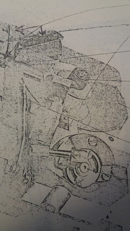
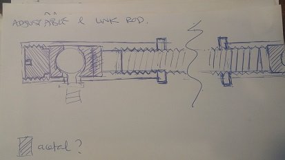
Adjustable mirror link rods Adjustable length might be very useful if they can be light enough. Ditto for adjustable ball cups. I have seen adjustable ball cup screws that went in axially, but I can't yet find a reference. An old, very faded, ACL I manual shows adjustable ball cup screws (I think) that screw in radially. Versions of an adjustable length rod that could be made simply seem possible. Just need to make them light enough for 75fps, which may be a fatal problem. The solution to accurate link rod length may be to accept the plastic and find a way to machine a simple cup positioned super accurately. Or just buy one from Les B if he is makes them. He probably would make them in a batches, assuming he thought this was a solution to something. Here is my doodle on an adjustable length rod with (acetal) plastic cup halves. Better version may come quickly to mind.. .
-
Duncan, Great stuff! I have done a near full tear down on 2-1/2 English 400' mags. Some of the parts look identical, and others are a different design. A toothed belt shifts power across the mag body to the take up arm drive spindle from where another toothed belt drives two little rubber tyres that run on the film. And the footage counter is a complicated little mechanical number counter with complicated drive system. And the take up arm spring tension adjustment has machinery and needs some deft handling. So there could be grounds for separating that one. I started a thread on those to bust some common myths about them and made a patchy attempt to document some of the tear down.. https://cinematography.com/index.php?/forums/topic/91664-english-acl-400-mags-facts-and-myths/ Back to the here and now.... I'm going to use the part names and numbers in the parts pdf, I'll just list some below and note your terminology in " ". I may use some shorthand, like dwg for drawing (not the file type) and assy for assembly. - 315E, in the 200' mag dwg is the feed sprocket assy. (Duncan..."thumbwheel in the take up side"). In the 400' mag dwg it is 730E but it doesn't show in a parts list. I think Duncan spotted that there is a page missing or something. - 325E, magazine drive assembly (Duncan..."drive spigot"). - 325, called driving axel bearing in the parts pdf, I'll call it the mag drive assy housing (Duncan..."the solid machined piece") Re the mag drive assy housing (325) being wiggly, not positioned precisely by the design engineering...I don;t remember the Eng mags being so, but it was a while ago. I do have a disassembled donor magazine here that is a mongrel...French throat, english body, take up system. This particular mag also has an imprecisely positioned (wiggley) mag drive assy housing. it looks like the machined surfaces should fit precisely in the chanel in the body, but no. I did notice that the loose fit of the screws was more on the ones further from the gear, so when you wiggle the housing the part near the gear is moving less. There is a good chance that my donor mag has been fiddled with. Some simple explanation may be there, like the Eng and French parts being different, and were swapped. I will at some point service the French mags I have, so will solve this riddle then. Meantime, if anyone knows the answer already, please spill. Gregg. PS: a correction re the transmision to the take up arm drive spindle above is in italics...
-
Thanks for posting those macro pics of the mirror. Now if Heikki measures the mirror axis position well have the good info.? For simplicity I'm going to refer to my drawing above. I get your point on the proximity of the mirror edge to the frame, with the exit of light from the rear elements of some lenses potentially hitting it. Do you think that light reflected from the edge of the mirror will raise the exposure evenly over the frame. Probably not. This is a problem peculiar to certain lenses perhaps. If a mirror edge was masking a frame corner at position A or B, that should be obvious on the exposure, so that peculiar problem also has nothing to contribute to the elevated exposure over the whole frame (EEWF). If the mirror positions L/R (A,B in drawing) are not symmetric about the aperture centre point, this is a function of link rod length. I always assumed that a new link rod was used for S16. I see that Les B also lists that on his S16 ACL mods. The link rods post ACL I are I think simple plastic. The ACL I had a metal one, some with clearance adjustable on the ball joints. Was metal abandoned for the high fps rates perhaps? An adjustable length metal link rod would be extremely useful. Obviously, if new link rods are made for S16, this may be a source of error. I'll reserve thoughts about that until I can understand the problem more deeply. The asymmetry in your pics is quite large. Interestingly, it favours the frame on camera L, where the S16 frame enlargement is. Is it possible that the shutter is one gear tooth out? I'll try and estimate the number of teeth from the parts drawing and calculate the angle increment. It may be too large to be a plausible cause. (once again we wish that I had one of Heikki's spare mechanisms sitting on my desk). Your mirror in position B looks clear of the frame corner by 2deg rotation, and a 180 tooth gear is not plausible, the vertical shaft has about 25 teeth. So mistiming I can't see as a cause of the asymmetry that you show. In Aapo style, I will proclaim that link rod length is the sole possible cause of mirror position asymmetry. And if this asymmetry causes unfavourable dynamic coupling, resonance allowed by the rubber drive block, then I've solved it! Time for a cup of tea. Gregg. PS: I'm getting the 9 pin connector replaced on my ACL II base v soon, then I can measure some things myself perhaps.
-
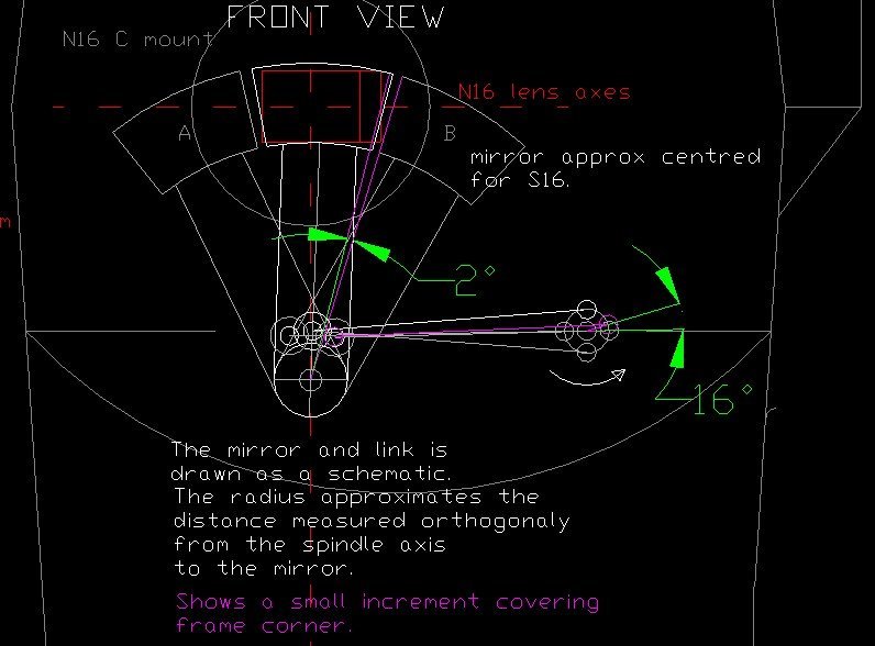
It may help if we have a drawing to refer to. This one shows an approximation of the effective mirror arm radius in a schematic, The mirror is oscillating on the surface of a cone. This can be represented in 2D using the effective mirror radius, measured orthogonally from the actual mirror spindle to the mirror. The "rim assembly" on the mag drive spindle is then also a schematic, giving the correct rotational relationships to the mirror arm. If I had the position of the mirror spindle axis relative to the lens axis I could put that in a drawing. I need to know the horizontal offset of the mirror spindle to the lens axis, hence if there is a cant angle for the mirror arm when centered on the N16 frame. Not all S16 geometry will be the same, so it's better to start with N16.
-
I understood what you meant with the 2% change in exposure of the whole frame, I looked at the increments of time and angle to achieve that and calculated a change in shutter speed. It would be oscillating between 24 and 24.47Hz. Then realized that I could just scale the shutter freq by 2%. And this was humorous because I thought that's what you and Dom had done earlier. Simpler. The "asymmetry" arising from the relationship of the mirror central axis and frame aperture is interesting to us both.? I can't tell yet if the unmodified camera (N16) has that and how much. My cam body has the base disassembled, motor off and I can't easily inch it or open the body on a whim. But I can see in my schematic drawing the scale and nature of the asymmetry that comes with the S16 mod. However, if we assume zero elasticity in the mechanical system, the "asymmetry'" of the mirror movement is hidden by the closed shutter. So lack of symmetry in the angular acceleration profile, L/R, is not relevant. But, if we accept that the mech system is elastic, then the mirror axis "asymmetry" may be a source of angular accelerations of the rotating elements, so the shutter. So examining whether some generic problem(s) underly the flicker with ACLs comes back to exploring a group of potential causes that may be acting, interacting in concert. I think it is misleading to proclaim that the only possible cause of flicker is the mirror. (edit: I mean the asymmetry in the L/R mirror positions). ? Instead, perhaps take the advice of Andrzej and explore with a crystal strobe. But lets not assume that what we discover on that camera will be true of all cameras. Gregg.
-
Prefix this with the caution that what one discovers about the particular is not automatically applicable to the general or universal.? We need to remind ourselves that the mechanism ideally would have constant angular velocity, so no angular acceleration, and the phases of the mirror movement (L/R) would be symmetrical. I think I have a plausible idea for how anomalous variation in friction could contribute to exposure variation over a two frame cycle. If we have bearing surfaces (bush and shaft) that are out of round on the mirror spindle or mag drive spindle, which both run at 1/2 the motor Hz, the friction peak would be every second frame. If this friction peak occurs when the mirror is in the left or right position, then the angular velocity on departure will be less than on the return stroke. So, a two frame cycle of exposure variation. Could the drive shaft in the mag, also running at 1/2 the motor Hz, have a friction peak? It having ball bearings, I tend to exclude it. We may be talking about small angular accelerations. Intuitively it seems like the inertial properties of the mechanical components will resist these angular accelerations, but the rubber drive coupler will enable them. So oscillation is possible. Normal exposure time with 175deg shutter at 24fps is 175/360/24 = 0.02026 seconds.The variation in the exposure time to give a 2% change in brightness is 0.000405 seconds for a 175deg shutter. Exposure time after that angular acceleration is 0.01986 seconds, and the fps=175/360/0.01986=24.47. Oh, now I see where Aapo got the 1/2 fps variation idea from. He just gave 24fps an extra 2%. Well, it was late, and now I'm laughing at myself. Another way to think about how the mirror assembly could cause angular accelerations of the shutter....Anything that allows a lack of symmetry in the two phases (L/R) of the mirror movement could cause angular accelerations in the mechanism. Most of the scenarios I think of allow the possibility of resonance. I'm thinking that at very low fps the inertial behaviour of the mechanism, the elastic behaviour of the rubber coupling and the likelihood of resonance will be much less. And this may be easy to test. I sent an email to Andrzej at AZ Spectrum. He is very busy but had some interesting ideas. It's easiest just to paste it... Wednesday, October 11, 2023 Hey Andrzej, I'm helping some research on why ACLs sometimes give an image that flickers. Do you have any insights into this? I posted some ideas on the cinematography.com forum... https://cinematography.com/index.php?/forums/topic/100490-eclair-acl-flicker-technical/#comment-583237 One possible cause is a ripple in the motor torque. The elasticity of the rubber drive coupling enables this impulse to be delivered to the mechanism, which has an inertial reaction. So any thoughts? Do the motors normally have perfectly even torque during one revolution? Do particular motors have a defect? Imperfect positioning of the hall sensors? Regards, Gregg. His reply..... Hey Gregg, Thank you for your e-mail. Currently I'm very busy with HD video taps installations. The problem you described you can resolve by using 24 Hz crystal strobe light. For the camera speed 24fps you can see in the 24Hz strobe light any vibration, of the motor speed, shutter vibration with magazine attached with film or empty. Problem can be related to motor, camera mechanism, mag, movement of the film and also to the power cable, battery or power supply. Best regards, Andrzej
-
Was the variation in brightness just for part of the frame, or for the whole frame? If for part of the frame, then the shape, location of that area may tell something about how it occured
-
Firstly, there may be generic characteristics of all motors that contribute to the flicker, but only show up when interacting with one or more other factors. Also, there may be characteristics of particular motors contributing to the problem. I sent an email to Andrzej at AZ Spectrum. Hope he's not too busy to reply. If there is an errant impulse or torque ripple (not sure of the best term)...I don't assume that its pattern cycles every two rev's. If it cycles every rev, I can imagine ways that it couples with the inertial response of the camera mechanism, such that the lag/lead at the mirror misplaces the mirror at critical moments. There will be some elasticity in the mechanical system of the mechanism, but, the first obvious place to look would be the rubber drive coupling. If errant impulses from the motors are eliminated as a cause, the rubber coupling could still be a factor, if other factors in the mechanical system interact to give angular accelerations that misplace the mirror, the rubber drive coupling will allow it, may even enhance it. Gregg.
-
Aapo, How did you get the exactly half fps exposure idea from? There may be several causes of flicker, some of them interacting. So our logic has to be extremely rigorous. For example, eliminating a motor as a cause in a particular case will not eliminate all motors as a potential cause in all cases. Regarding the mechanical properties of the camera movement as a system. There is some elasticity in the behaviour and if a momentary angular impulse comes from the motor, smoothed and enabled by the rubber coupling, the mirror arm may respond. It may be a simple lag/lead response to the impulse. First thought is that the mirror arm is too stiff to contribute to this, or to have natural vibrational modes of low enough Hz or big enough amplitude. But a lag/lead effect may come from play in the mechanical system, likely the clearance in the link rod ball joints for the obvious example. The rubber drive coupler may not damp the motor impulses. It may make their effect worse, smoothed somewhat but delivered effectively to the mechanism. It may help if we get a feel for the significance of tiny increments in critical parts of the system. I don't have an open mechanism at the moment, so I had to approximate to draw a schematic of the mirror with arm, link rod and "rim assembly" (83E). The rim assembly is at the end of the mag dive spindle assembly, with a ball for the link rod. So I approximated the effective radius of the mirror from the mirror support spindle (part 80). I made a schematic that allowed me to enquire about angles. If anyone can give me the dimensions of the mirror arm I can do this better. Suppose the mirror intrudes almost 1mm into the corner of the aperture during exposure...this is approx a 2deg increment for the mirror arm, and a 16deg increment for the "rim assembly". If I knew the mirror arm dimensions I could say what the movement of the ball joint was to achieve that (about 0.18mm)...... Remember the mirror arm assembly is as if on the surface of a cone, with the radius to the mirror measured orthogonally to the cone's central axis. If I can find dimensions for the mirror arm assembly I will post a drawing. Gregg.
-
Hey Dom, Your ideas and experience with it seem in line with my intuited suspicions. I was wondering about resonance between motor torque variation and the natural vibration behaviour of mechanical components, probably the mirror. Now I wonder if the cyclic variation in friction could also contribute to resonance. I don't have an academic background that lets me explore this directly with math, but maybe we can take a simple approach to remove the potential contributions. I'm going to ask Andrzej at AZ Spectrum about possible uneven torque from the motor. Actually, various people will understand the motors well enough to give some ideas on that. Maybe the motor is sometimes a contributor and some times not. There was another possible cause of flicker that I forgot to include. The machining to the camera body for some S16 conversions had made a tiny hole. Heikki had one of those cameras and made some documentation about it. We should find that and link to it or paste it in. I corrected a stuff up in my first post above. Now the relative frequency of the mirror and motor is clear. If motor (at 24fps) is 24Hz, the mirror is 12Hz. Gregg.
-
The recent post on ACL flicker from the Fleamarket thread.... Or you can go there https://cinematography.com/index.php?/forums/topic/91893-eclair-flea-market/page/4/#comment-583224 steven jackson Posted 15 hours ago (10th Oct..?) I'm going to sell a super16 ACL body that according to Paul at Visual Products, was modified by him, but for some reason was never fully finished...meaning that it does not have a VP ground glass, but a standard ground glass. It's just the body, no motor or viewfinder, so would suit someone that already has an ACL and wants to swap over a few parts to have a super16 camera. I've shot film with this camera on numerous occasions and the results are good but under certain situations, mostly backlit sunlight, I get flicker, which was easily dealt with in DaVinci. I won't be asking a fortune for it. aapo lettinen Posted 13 hours ago 15 hours ago, steven jackson said: I've shot film with this camera on numerous occasions and the results are good but under certain situations, mostly backlit sunlight, I get flicker, which was easily dealt with in DaVinci. I won't be asking a fortune for it. I had a discuss with Heikki about this weird flickering of ACLs under certain backlit conditions and I guessed it would be caused the slightly asymmetric movement of the mirror which causes every other frame to receive just couple of % more exposure than the other. Heikki sent me some test footage and I confirmed that it is indeed exactly every other frame being slightly different exposure than the other so it has to be caused by the slightly asymmetric movement of the mirror. I don't know if it can be corrected by timing the mirror differently but all cameras don't seem to do it so I guess it can Heikki Repo Posted 13 hours ago The backlit sunlight flicker is a different issue compared to the one we discussed Aapo - it's a feature present on all ACLs due to the way the mirror works in this camera. It's not a bug. The flicker that's present in the footage I sent to Aapo on the other hand is present on every other frame regardless of the lighting situation. That one is due to very slight higher friction in the movement and has been generally noted by Visual Products to be the difficult to solve cause of flicker in some ACLs. In order to solve that one one has to be able to make the movement smooth without any bumps in friction. steven jackson Posted 12 hours ago (edited) Paul Scaglione from Visual Products did tell me this too. Is this flickering from your newly converted ACL from Les?? Duncan Brown Posted 11 hours ago Wasn't there a whole other cause of flicker that had to do with light sneaking in around the recentered lens mount on a S16 converted camera? I'm sure I read that somewhere around here. But it sounds like you are talking about potential flicker on even a stock ACL. Heikki Repo Posted 9 hours ago 12 hours ago, steven jackson said: Is this flickering from your newly converted ACL from Les?? No, this is on one of the ACLs I have serviced. Still haven't had time to finish tests on the newly converted one...
-
Attempting to gather any technical ideas about ACL flicker here. The prompt was some recent informal posts in the Fleamarket thread. I'll offer some introductory ideas then paste those... ACL Flicker. Introductory...what causes it? 1) Is it generic to ACL or is it a fixable fault? Are ther multiple causes? 2) On both N16 and some of the S16 conversions, is flicker caused by)? - Mirror off position due to wider aperture? - Mirror off position due to timing. - Mirror off position due to link length. 3) Stray light from the mirror? The mirror face or the edge? Can that light be controlled with black paint? 4) Uneven friction in a rotational cycle? Hoping Paul can explain that... 5) Mechanical connection between the motor and claw control shaft, the rubber coupling (20). 6) Resonance. 7) Light leaks in the body casting, such as from S16 machining errors. Can careful examination of the negative or scan show what the flicker is in the frame. Is it a dark area or a bright area? I have yet to understand points 4) and 5). I get that small angular accelerations (uneven angular velocity during a rotation) could cause the mirror to have lead/lag with its position, but I don't know more. Hoping that Paul does. On the rubber coupling, Dirk DeJonghe once commented that replacing that was a common fix for ACL flicker back in the day. I wonder if uneven torque from the motor, cushioned by the rubber coupling, would give these small angular accelerations. The torque could pulse within one revolution, or within a cycle over two revolutions, and some resonance is possible with the natural mode shapes and frequencies of the mirror vibrations. This could lead to the mirror being a tiny bit out of position at the wrong time. I'm guessing a bit, but instinctively I look for resonance between the motor and the significant elements in the movement. The mirror, with its 2 motor revs (2 frames) per cycle and long arm feels likely. If the variation in angular velocity was frame by frame then this could also account for variation in density, flicker. The ACL mirror movement. I'm going to look at the ACL mirror movement. Back later..
-
Eclair Flea Market
Gregg MacPherson replied to Gregg MacPherson's topic in Marketplace Listings Under $200 / €200
Often, interesting topics are informally started within other topics, and this way are more easily lost downstream, hard to find later. I'm going to start a new topic on ACL flicker and transfer the content above to there. Anyone can do this (hint). Gregg. -
Eclair Flea Market
Gregg MacPherson replied to Gregg MacPherson's topic in Marketplace Listings Under $200 / €200
That one seems, in a relative sense, like quite a good deal to me. It's been out of circulation for 10 years and was owned, used by someone competent who will have kept it serviced. It doesn't have PL mount or 75fps but otherwise it's a good kit list. If you could buy direct from him without eBay success fees and Paypal fees it would be about USD8K. It's being offered at about half the value that XTRs are selling at. But taking Steven's point, maybe cameras are overvalued. If we consider the liabilities with the shrinking resource of skilled techs and parts, maybe caution is due. But we can't be too influenced by the historic low point in prices from a few years ago (the Happy Times). One thing worth considering...the value of a camera varies with particular buyers, how well their knowledge and location solves the proximity or access to servicing and parts. It's a worthy topic, but if we get serious we may need another thread. -
Eclair Flea Market
Gregg MacPherson replied to Gregg MacPherson's topic in Marketplace Listings Under $200 / €200
Hey, I had a look. He's a good salesman, and has done some interesting mods and accessorising, the video tap result looks really good. But there are some defects, downsides and serious unknowns. Not being morbid, but...(maybe I am) - When was the camera last serviced? What would the techs notes on it's condition and mileage look like? - The GG markings are almost unusable. it needs cleaning up and re marking, even if just with pencil etc. - Why is it flickering? - The gate looks quite scratched, maybe it's done a lot of work. High mileage without regular service, if that's what's happened, is bad. - The VF is my least favourite type. It's quite low for shoulder mounting. I don't mind the early swiveling, non orientable Ang or tube periscope VFs, but I'm not fond of this low Kinoptik one. - The lack of good mount adapters devalues the kit. PL/C is not a good permanent solution. - The mag set is not great, and the description of the relative friction concerns me. Maybe film was not loaded. My comparison between Eng and French 400' mags current draw, the freshly serviced Eng one was 30% less A. - The rod base places the LWS rods very low. Maybe one can adapt some MB to that, and his FF servo gear reaches ok, but I don't know if a Chrosziel or Arri FF swing arm will reach at a usable angle from there. Gregg. -
PL mount for 8 hole Zeiss ex Slomo Digital
Gregg MacPherson replied to Gregg MacPherson's topic in Lenses & Lens Accessories
I just had the rear light baffles made that I needed for the Slomo PL mounts. Turned on a manual lathe. Coated really inexpensively with Ferrophos. Total cost was about USD60 each, but I don't know if the machinist enjoyed it. Unfortunately we did not go to CNC, otherwise there might be a cheap source of these parts. If someone wants to prep for CNC we might share the 2D Autocad drawing. https://www.dropbox.com/scl/fi/1grcrzzdv131ga53d1toh/light-baffles.jpg?rlkey=p0zajtc2qxjm296tqcqa4eepa&dl=0 The one on the right is an original Zeiss/Arri part fitted to a Slomo PL mount. I don't assume that all baffles have the same inside dimension fitting over the lenses, but the Zeiss one from the 16mm format f=50mm lens looked like it would fit the other 16mm format lenses. When I know for sure I will report. Gregg. -
Rod base, bridge plate/dovetail solutions for ACLs
Gregg MacPherson replied to Gregg MacPherson's topic in Eclair
The other thing we did not consider yet is the tie down screw offset. Proaim give the position of the 3/8" tie down screws as being centred on the 19mm rods, but ACL 2 has the screw about 9mm offset to camera left. I'll update that drawing. Doesn't look like there is room to make a new hole or slot in the bridge plate. One needs to tap a new hole in the camera base. Does anyone know if the 3/8' tie down taped hole is also offset in the ACL 1 and 1.5 base? To be clear, the offset referred to is horizontally from the lens axis. -
Rod base, bridge plate/dovetail solutions for ACLs
Gregg MacPherson replied to Gregg MacPherson's topic in Eclair
The ACL 1.5 lens height (distance from the camera's lens axis to the bottom of the base) looks very close to lining up to the matte box axis on the CH-DTPQ-01 bridge plate. Heikki could check.? -
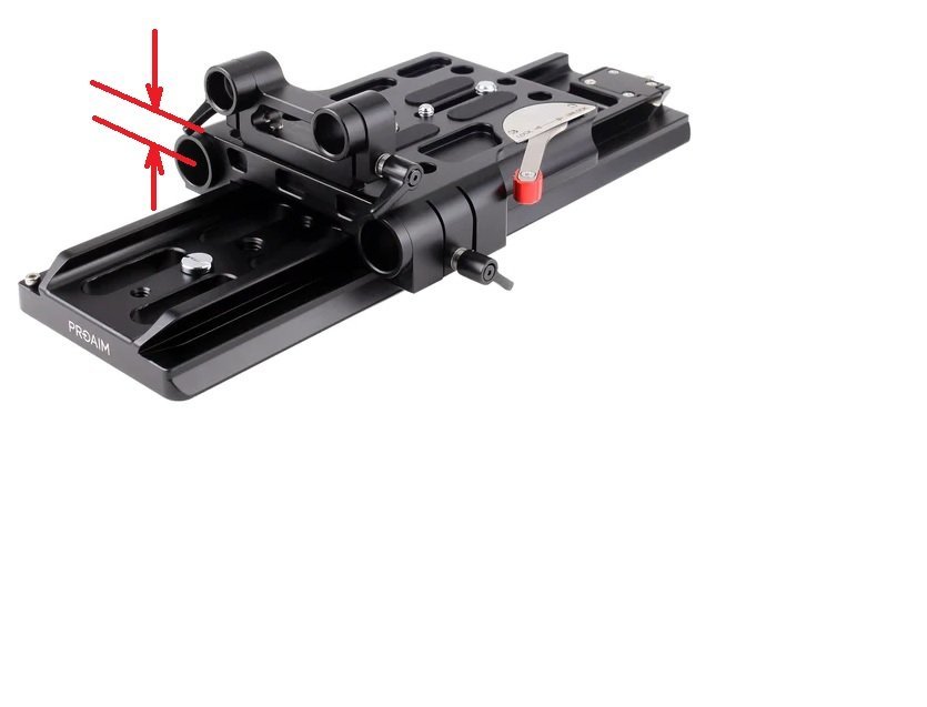
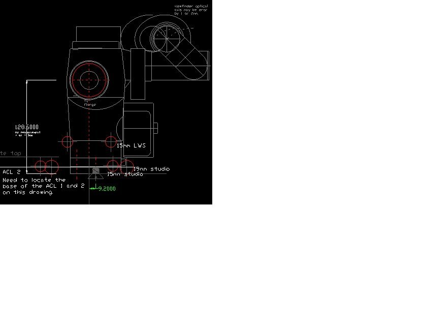
The ACL 1, 1.5, 2 all have a different vertical dimension between the lens axis and the bottom of the base. Hence, adapting generic accessories to these cameras can be problematic. ACL 1 could be given a spacer to raise the base, but ACL 2 is too tall, unless the rod clamp can be packed up. The 1.5 may be close to OK on generic base plates/bridge plates. I'm hoping that Heikki will measure the vertical dimension on his 1.5. Here's a drawing of the ACL 2 with all rod positions shown, 15mm LWS, 15mm studio, 19mm studio...If you print the pdf below at 100% it will be 1:1 scale. There's a link to Arri's drawing with the rod position dimensions at the bottom of this post. ACL rods and camera base w tie down.pdf It would be useful to know the position of the ACL 1 and 1.5 base on that drawing. One could measure on the camera. An accurate mark for the lens axis on a lens cap (the centre), then measure vertically down to a flat bench. A builder's square helps. Ready made solutions for mounting 15mm LWS rods on ACL 1.5 and 2 (and maybe ACL 1) are available as rod mount brackets (plates) that screw to the camera base. Les Bosher's version for example. These designs are monofunctional. Multifunctional designs can obviously be more useful and from a design perspective they are very interesting. The support (base plate/bridge plate) immediately under the camera might have multiple functions including some or all of... - Rod mounts for 15mm LWS/15mm studio/19mm studio - Dovetail interface for balance. - Accepts a shoulder mount. - Enables mounting batteries to the rear - Rossetts for front handle sets The Proaim bridge plate/dovetail CH-DTPQ-01 came up on the forum recently and was favourably reviewed. (the dimension in red, Proaim gives it as 14mm) The Proaim page may change, but here it is... https://www.proaim.com/products/proaim-19-15mm-camera-base-plate-with-dovetail-tripod-plate-arri-standard Proaim, manufacturing in India I think, have a history of cloning/paraphrasing generic high end industry gear. Out of design curiosity I bought, a few years ago, cheap, used, a Proaim 4x5.65 swing away MB and a studio FF that looked like a Chrosziel. They both had some really good design engineering but were let down by (literally) one or two really small but sometimes fatal errors. So I've always been interested in ideas from Proaim. The CH-DTPQ-01 would be an inexpensive way to enable 19mm support for big lenses. Does anyone know if 3/4" (19.05mm) tube will fit generic 19mm machined rod mounts. Thin walled chrome molly steel would be an easy way to get stiffness, but I've only seen it in Imperial sizes. (Edit: I just tried some imperial 4130 tube on the Proaim and it fitted well. I wonder if Arri 19mm hole sizes would also fit. If mounting the ACL 2 on this bridge plate the lens axis would be too high for the integral 19mm rod mounts, but some adaptions could be possible - custom risers for the MB and lens support. I wonder how close to OK the ACL 1.5 lens axis is. If not using the 19mm rods for MB or FF then the 15mm rod mount can be packed up to height. This bridge plate adds some height and if a shoulder pad is mounted under it the result may shift the camera too high, considering the eyepiece position and the sense of balance and stability. The dimension in red in the photo above , Proaim give it as 14mm. If you want to measure the height of the lens axis on your ACL 1 or 1.5 that would be really useful. (thanks in advance) If you have any experiences adapting an ACL to generic bridge plates, rod mounts feel free to share here.... There is an Arri drawing showing the measured positions of the various rods relative to the lens axis here... https://thecinelens.com/2014/01/27/iris-rods-a-simple-explanation/ Gregg.
-
WTB: Bridge plate + Dovetail
Gregg MacPherson replied to Boris Kalaidjiev's topic in Cine Marketplace
With the ACL 1.5, do you know the vertical height from the 19mm rod centre to the lens axis..? Do you know the vertical height of the lens axis on the 1,5 (measured to the bottom of the base). I might start a thread about this bridge plate on the Eclair forum. The 19mm rods could give really stiff support for very big lenses. I messaged the Proaim sales guys asking re the the vertical distance from the face of the bridge plate to the 19mm rod axis.. This is probably copying the dimension from an Arri bridge plate.
-
WTB: Bridge plate + Dovetail
Gregg MacPherson replied to Boris Kalaidjiev's topic in Cine Marketplace
Please ignore that string of discarded text after I signed off... Heikki, maybe some basic info about this Proaim CH-DTPQ-01 unit could go onto the Eclai forum. Solving the iris rod height well for ACL can be tricky and this Proaim one may give some useful options. Gregg. -
WTB: Bridge plate + Dovetail
Gregg MacPherson replied to Boris Kalaidjiev's topic in Cine Marketplace
Which ACL are you using it with? The ACL 1, 1.5, 2 have different vertical dimensions between the base bottom and the lens axis. The ACL 1 may be too short and the 2 is definitely too tall, but the 1.5 may be close to correct. So the matte box will line up for ACL 1.5? The 19mm rod clamps are integral, fixed, but the 15mm clamps could be adjusted up with a spacer. It would be useful to know the vertical distance from the face of the base plate to the 19mm rod axis. Perhaps one could measure with a vernier from base plate face to the inner surface of that rod clamp. You can see the Arri reference drawing showing relative positions of rods to lens axis here. Does anyone know where the Arri base plates sit in that drawing (the top face)..? https://thecinelens.com/2014/01/27/iris-rods-a-simple-explanation/ Gregg. If you mount the camera and measure from th -
Link to the KameraDoctor guy Danil.. DANIÍl NEVSKIJ KINOTECH https://www.instagram.com/kamera_doctor/?hl=en Good contact. Thanks Evan. Does he work on Eclairs? Gregg.
-
The DIN 920 standard is a 2.8mm diam cheese head. The recess for the screw heads in the Zeiss PL mount is designed to take those screws.I don't know if all the 3rd party PL mounts copy that exactly. There isn't much metal there to make the diameter much bigger. The sample screws I got with the 3rd party PL mount from Slomo were I think 3mm head diameter, They fitted their mount, but I didn't try them on a zeiss mount. The DIN 920 screws are absurdly cheap in large quantities, and absurdly expensive in small quantities, with silly shipping costs. Cheers, Gregg.
-
I did buy 8mm long screws from Accu in the end, a few months ago. This length I took from a Zeiss drawing for a standard speed. Earlier I had found the screws for the 16mm format, 50mm superspeed factory PL mount to be 6mm long, but I foolishly bought 8mm screws thinking they would have better thread engagement. Of course they were too long..! Luckily Accu screwed up the shipping so I didn't pay for that. When I look at the screws that Accu supplied, the last 1mm or so is not well formed, so this decided me on trimming the screw length rather than ordering more screws, which is surprisingly easy. The available space in the threaded hole on the (16mm format) s'speeds may actually be something like 7mm, but I decided I would (should) just use the screws of the same length as the sample, 6mm. Bit of a screwup really..ha. Gregg.
