Nicolas POISSON
-
Posts
88 -
Joined
-
Last visited
Everything posted by Nicolas POISSON
-
If you are monitoring the log signal, this is the expected behaviour in Cine EI mode. Apply any LUT and you will see the changes.
-
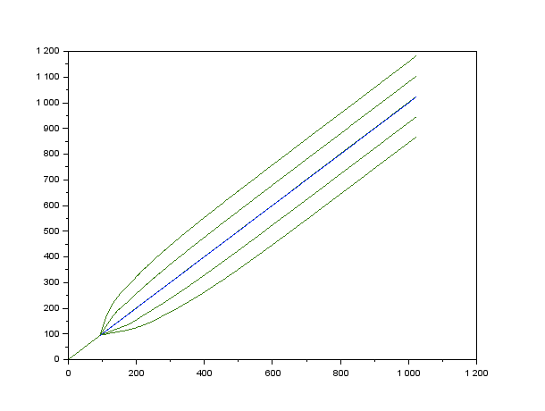
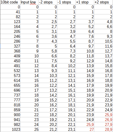
This is just the good old principle of exposure compensated LUTs on an external monitor. I guess most people here are familiar with it: create “Log to Rec709” LUTs that darken or lighten the image by 1 stop increment, send them to the monitor, and use them as an EI scale instead of the DSLR analogue ISO (which you leave at the base value). The point here is to create LUTs using maths and DaVinci Resolve. There may be simpler ways to do this with CSTs, but this is a topic I know nothing about. And part of the fun was to do it myself as a pedagogic exercise. What I tried before: 1- shoot a scene with a middle grey card in it. Set the exposure according to the manufacturer advice and keeping ISO at its base value. Then shoot 1 and 2 stops overexposed, 1 and 2 stops underexposed. I guess the best is to change shutter speed (same depth of field), but aperture does the trick. Import all the stuff in DVR. Add the “Log to Rec709” LUT as the last node. Then add a second node before, and adjust offset with SDR wheels, or global exposure with HDR wheels, so that middle grey goes back to the reference. HDR tools work better, but both are far from perfect. 2- same as before, but fine-tune using whatever colour-correction tools you want (especially contrast, saturation, and the curve tool), so that compensated images visually match the normally exposed one. This is a trial-and-error method that leads to better results. But not very scientific. After that, sandwich the colour correction node together with the “log to rec709” in a single LUT (one for each compensated exposure), send them to the monitor, and use them instead of the DSLR analogue ISO. You get Sony’s “Cine EI” feature on any DSLR. This works well for mid-tones, and this may be enough on set. But this can be improved. LOG profiles are documented. Manufacturers give the formulas to switch from real world scene reflection to log coded values, and the other way around. Thus: - starting from a recorded log signal, we can find what was the reflection - compute what would have been the scene reflection if the sensor had been exposed 1 or 2 stops higher/lower - from that simulated exposures, find what would have been the log codes for these reflection. We can compute the curves that make a 1-2 stop over/underexposure look like if it was correctly exposed. I used Scilab to program this, but this can be done in any spreadsheet program. slog3.sci Here are the curves for SLog3: Note: these curves are log space to log space, and SLog3 does not go below code 95 (10bit scale). The curve shape below 95 does not matter. As the compensation curve will be drawn manually in Resolve, it helps to determine the points corresponding to the grid of the curve tool (25 intervals ranging from 0 to 100% Luma). Here it is for SLog3: A few more notes: - the curve tool in DVR uses splines, which do not allow for sharp edges. It may be better to have the lowest point at coordinates [0, 95] rather than [0, 0]. - upward compensation leads to values above 1023 (above 25th grid line). The best way to handle this is probably to draw manually some kind of highlight roll-off. - From what I tested, 5-8 points are enough to define the curve (example below for Fuji F-log) This gives a much better base than playing with offset or HDR exposure. This is still not perfect and I had to bring up lowlight saturation a bit for the negative compensation LUTs, and bring it down for positive compensation LUTs. But I could get good similarity across LUTs tweaking very few controls. Here are the results on Fuji F-log, starting from +2 stops compensation (underexposed sensor) to -2 stops (overexposed sensor). The 3rd image is the reference, exposed normally. +2 stops (sensor underexposed by 2 stops) +1 stop Standard exposure: -1 stop -2 stops The curtains lost all details in the 2 stops underexposed shot. Even with “only” one stop underexposure, there are quantization problems near the gray card, where the magenta turns into brown. My understanding is that my camera’s Dynamic Range (Fuji X-T30) is centred at +/-5,5 stops around middle gray at standard exposure. Underexposing the sensor by one stop leads to only 4,5 stops below, which I expect to be too low for many situations. Highlights do clip in the 2 stops overexposed shot, visible in the specular reflection on the tiny aluminium PAR spot. However this scene does not contain much highlights, thus it does not appear that terrible to me. Following other tests I made, the most common exposure I would use is overexposing the sensor by 1 stop, which sets the DR at +4,5 / -6,5 stops around middle grey. Comparing to other manufacturers, this asymmetry toward low light seems common. Depending on the scene, overexposing by 2 stops might even be acceptable. Thus, I could think it as “the nominal exposure could be 1 stop above what Fuji says”. Final reminder: write it down somewhere and tell the colorist. The meta-data claims ISO 640 whatever the LUT.


-
How does dual native iso function?
Nicolas POISSON replied to silvan schnelli's topic in General Discussion
When bypassing the capacitor, both the noise floor and the clip threshold are lowered. This does not change the dynamic range: the ratio remains the same. It is like saying 1000 to 10 has the same ratio as 100 to one. What you gain in noise is what you loose in highlights. The lower base ISO does not get obsolete as: - the whole DR is unchanged - base ISO of 800 is more convenient for well lit scenes, which are probably more common than low light scenes. For instance, you are shooting outdoors during a sunny day. Using base ISO 800 and EI 800, you set-up your aperture so that 6 stops above middle gray and 10 stops below fit your needs. If you were to switch to base ISO 3200 EI 800, you would have the same exposure, but now only 4 stops above middle gray. Your highlights are clipped. To avoid that, you either need to close your aperture by 2 stops, or put 2 stops of NDs on your lens. At the end, you get the exact same noise and clipping relatively to your scene... but you need ND filters. When switching from a lower to a higher base ISO keeping EI the same, you cannot apply the usual rule that higher ISO (indeed, higher EI) protects your highlights. This is the exact contrary. It does not help that "ISO" is often used instead of "EI", which made no confusion until dual base ISO was invented.- 1 reply
-
- 1
-

-
Why are shutter-speed calculations not linear?
Nicolas POISSON replied to Michael Althaus's topic in General Discussion
If you want to calculate intermediate 1/3rd stops values of aperture, you have to cumulate the cube root of 2 (1/3rd stops) and the square root (radius vs. surface). This time, the basic maths are: (X^a)^b = X^(a*b) The multiplier becomes : sqrt(2^(1/3)) = ( 2^(1/3) ) ^ (1/2) = 2^(1/3 * 1/2) = 2^(1/6) = 1.122 For example, starting from f/2 f/2 f/2+1/3 = f/2.2 f/2+2/3 = f/2.5 f/2.8 f/2.8+1/3 = f/3.2 f/2.8+2/3 = f/3.6 f/4 ... -
Why are shutter-speed calculations not linear?
Nicolas POISSON replied to Michael Althaus's topic in General Discussion
My understanding is that it has more to do with the way human perception works. It just happened that film follows more or less human sensitivity to light. Audio levels are expressed in decibels, which is also a log scale (base 10 instead of 2), although recording medium are not inherently logarithmic. But human hearing is. For the maths: it is just the property of x^(a+b) = x^a * x^b. The simplest example could be x^2 = x^(1+1) = x * x. In our case: 2^(log(1000; 2) + 1/3) = 2^(log(1000; 2) * 2^(1/3), and 2^(1/3) is the cube root of 2. Since the scale is usually split in 1/3rd of a stop, there are only three values to memorize, then you can guess all the other ones multiplying by 2 (one stop). If you were to use a scale in half stops, then the multiplier would not be the cube root but the square root of two, and there would be only two base values to memorize. If you want to use 1/10th of a stop (some light meters use that), the multiplier is 2^(1/10) = 1.072. By the way, the aperture series follows a square root of two, but for a complete different reason: there is a full stop between f/4 and f/5.6, not half a stop. It is just that photographers chose to express the series using the radius of the aperture, instead of its surface. Things would have been much simpler if the aperture scale was: 1 (instead of f/1), 2 (instead of f/1.4), 4 (instead of f/2) 8 (instead of f/2.8) 16 (instead of f/4) 32 (instead of f/5.6) 64, ...and so on. -
Why are shutter-speed calculations not linear?
Nicolas POISSON replied to Michael Althaus's topic in General Discussion
Stops are a logarithmic scale. 1/3rd and 2/3rd of a stops are not linearly spaced. Otherwise it would mean full stops follow a logarithmic scale but intermediate values follow a linear scale, which would make a complete mess. In Excel (enclosed file), the formula is: Shutter speed -1/3rd = 2^(log(reference shutter speed; 2) + 1/3) Shutter speed -2/3rd = 2^(log(reference shutter speed; 2) + 2/3) Starting from 1/1000th of a second, this gives: 1/3 stop below: 2^(log(1000; 2) + 1/3) = 1/1260s 2/3 stop below: 2^(log(1000; 2) + 2/3) = 1/1587s The series repeat with a factor of 2. Starting from 1/50th of a second: 50 - 63 - 80 100 - 125 - 160 200 - 250 - 320 400 - 500 - 640 800 - 1000 - 1250 1600 - 2000 - 2500 3200 - 4000 - 5000 6400 - 8000 - 10000 12500 - 16000 - 20000 Some values are rounded to help the memorization. For example, 2x640 should give 1280, not 1250. But then the following figures would be 2560 instead of 2500, 5120 instead of 5000, and so on. Or the other way around: 1250/2 should give 625 instead of 640, then 312.5 instead of 320, then 156.25 instead of 160. I am not sure, but I guess the actual value used by the device is very precise. It is just the way it is labelled that is simplified. By the way, the ISO follows the same scale, for the same reason. As do frequencies on an audio graphics equalizer (octave is logarithmic scale like stops). The rounded value sometimes differs a bit. In audio, it is common to find 315Hz and 630Hz instead of 320 and 640. For historical reason, there might be some additional shutter speed values that do not follow the logarithmic scale, such as 1/48 and 1/96 (multiples of motion picture 24fps) ,1/60, 1/120, 1/180 and 1/240 (60Hz countries). Using a photo lens with a clicked aperture, you will not be able to respect the triangle of exposure, as you will not have the required ISO or diaphragm intermediate values to compensate. But that is hardly a problem since in videography, one rarely use shutter speed as an exposure parameter. And even if we do, The difference between 1/48 and 1/50, or between 1/60 and 1/63, is so small that it is nothing you cannot manage in post. With a de-clicked aperture, you could compensate exactly, but I very much doubt you could be that precise. stops_calculation.xls -
Camera Dynamic Range (DR) vs Display
Nicolas POISSON replied to silvan schnelli's topic in Camera Assistant / DIT & Gear
In a basic system, video cameras have a gamma of 0.45 (OETF: Opto-Electronic Transfer Function) to compensate the inherent gamma 2.2 of CRT (EOTF: Electro-Optical...). The whole chain has a gamma of 0.45*2.2 = 1 (OOTF), which means the brightness output by the CRT is simply proportional to the scene brightness. The problem is the rather limited DR, which is often described as a clue of "video-ish look". Even in the analogue era during the 90's, some pro video cameras had highlight compression, which means the OOTF was not linear. Consumer cameras, however, mostly used the gamma 0.45 curve. A Sony TRV900 - a popular consumer DV camera - could deliver like 6 stops of DR. Things started to change in the late 2000s, especially when photo cameras entered the video market (the famous Canon 5DmkII was released in 2008, IRC). Both cameras and displays improved, but backward compatibility was important. The solution was to keep a 0.45 gamma curve for levels up to the mid-tones, and then use highlight roll-off ( =compression). What was formerly a pro feature became very common. At the beginning, this was presented as an additional "cine profile". But nowadays, the limited "pure gamma 0.45" must have disappeared from most cameras. All built-in looks do have a more or less pronounced roll-off. No video is faithful to the scene luminance since the last 15 years. -
Camera Dynamic Range (DR) vs Display
Nicolas POISSON replied to silvan schnelli's topic in Camera Assistant / DIT & Gear
DR is tied to bit depth only if the coding is linear. But this is not the case at all for most displays. Common colour spaces, such as Rec709, sRGB, or cinema projection, all use a gamma curves to define the relationship between luma (0-100% form black to white) and real world brightness. Codes in the lower end are much closer to one another. Although the origin was related to the way Cathode Ray Tubes work, this also more or less follows the capacity of the human vision to distinguish light levels. This is a very rare case of a technical non-linearity being favourable, even decades later while CRT have disappeared. LCDs still mimic the response of CRT, and this is not only for backward compatibility: even if we could completely forget about CRT, it would still be a good idea to use a non-linear curve. We might use a Log curve instead of gamma curve, but that would not be that much different. Display DR depends on the definition you choose. To my knowledge, there are at least three: - display contrast: this is the ratio of peak white to "black" level. LCD displays (whether TN, IPS or VA) are not pitch black when luma is 0. A consumer IPS panel is typically around 1200:1 to 1500:1. Some other technologies, as OLED, have true blacks and can be considered to have an infinite contrast ratio. - ratio of the peak brightness to the tiniest difference between two adjacent levels in the whole brightness scale. Usually this tiniest difference is between the lowest and second lowest levels. The value depends on the gamma curve. In Rec709 with a theoretical 2.4 pure gamma curve on a display with infinite contrast, the order of magnitude is a 1:1000 ratio (10 stops). - ratio of the peak brightness to the threshold above which adjacent levels are close enough so that the human eye cannot distinguish them. This is the criteria used in the BBC white paper WHP309 about HLG. The order of magnitude is 1:40 ratio (5.27 stops). There are luma codes below, but they translate into differences in brightness that the eye is able to see. There could be an additional definition: real world DR. For example, if the light output by house lamps falls on your screen, it will hide the darkest details. This cannot be determined as a specification since it depends on the viewing conditions. But this is of up-most importance and this explains why, when producing for consumer TVs, web or (worst case) smart-phones, one might prefer to stay away from the darkest levels since there is a high risk that the viewers will miss them. What happens if the camera can record more stops than the display ? This is up to the production. It can be simply clipped. But most of the time, this will be "compressed": differences in high brightness levels will be reduced compared to what they would be if the curve was a pure gamma. This is the common "shoulder" part of so many tone mapping curves. -
Best all round on camera monitor?
Nicolas POISSON replied to Daniel O'Flaherty's topic in General Discussion
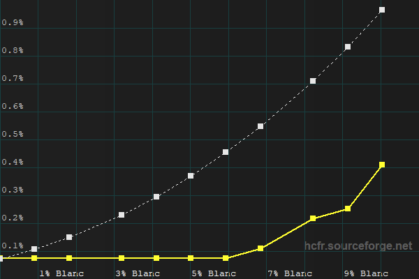
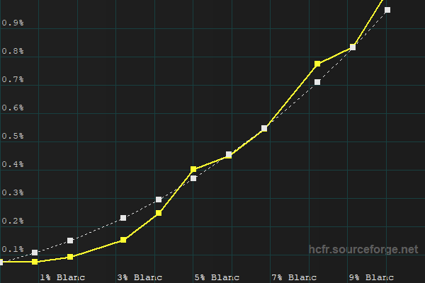
Answering to myself. It seems that the default calibration of the Ninja V targets a pure Gamma 2.4 law, ignoring the non-zero black level of the display. Here is a comparison of the Ninja V in "Native" mode and the pure gamma 2.4 law: Reading right to left: the measured curve (plain yellow) matches the reference (dashed white) until the display reaches its inherent black level. Then the lower 5-6% luma levels cannot be distinguished. Now here is the same "native" mode compared to the expected BT.1886 curve considering the black level of the device: Using a LUT, It is of course possible to calibrate the device to follow BT.1886: Lower-but-not-lowest levels are raised, so the image appears a bit washed out. For a medium to high key image, it moves away from what a user watching the same image on a high end OLED panel would see. However, the Ninja V has a 1300:1 contrast ratio, which is very common value for an IPS panel. Calibrated to BT.1886, the image is much closer to what a user watching an decent IPS display would expect. Note for those interested: to calibrate the Ninja V properly, you have to activate an "Identity LUT" first, otherwise the calibration will be off. The Ninja V deactivates some internal calibration when using LUTs, and once you calibrate it, then, well, you will be using LUTs.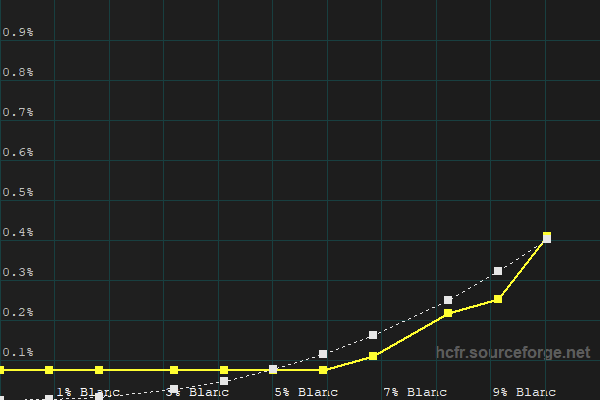
-
High microcontrast lenses
Nicolas POISSON replied to Pablo Cruz Villalba's topic in Lenses & Lens Accessories
I guess many modern still lenses would fall in that category. It is common now to have them super sharp, with great resistance to flare and high micro-contrast. Are you searching lenses for still photography ? -
Exposing for Monochromatic Lighting
Nicolas POISSON replied to Jonas Schubach's topic in Lighting for Film & Video
Can you have access to a "Parade" measurement, for example on an external monitor ? In which case you could check the red channel. By the way, because of the Bayer CFA, deep red lighting will also strongly decrease the perceived sharpness. The same would happen with deep blue lighting and in a lesser extent deep green lighting. You may be interested by this thread: -
I think there may be a question of wording here. In physics, the concept of "diffuse reflection" means a beam of light made of parallel rays will be scattered in every direction. However my understanding is that in the film-making world, "diffuse light" refers to a source that is both large and with a rather wide beam. That may not be scientifically correct, but I think this is the way it is commonly understood. Although it is possible to create a big source emitting strictly perpendicularly to its surface, such a device will rarely be encountered in practice. LED panels emit with a certain angle. An object close to these panels will have soft shadows, because it still receives light from a great surface. Even panels with very directive LEDs will create rather soft shadows at proximity. The angle of each individual LED is wide enough to blend with a significant amount of neighbours. Soft-boxes with honeycombs will act the same. You can find exceptions, such as this DIY parabolic reflector that is both huge AND creates hard shadows.
-
A diffuse light is not the same as, nor is contrary to, a directional light. Soft shadows are the result of a light source being big compared to the distance to the object. This is just basic geometry. It does not matter if it is a medium size source close to the object or a bigger source a bit farther away. A 60cm square source at 1m will give the same shadows as a 1.2m square source at 2m, or a 1.8m square source at 3m. Diffusion very close to the source will not make shadows softer, it will spread the light. Adding diffusion on a narrow beam source will light a greater area. Some areas that were not in the beam will now receive light. The trade-off is that areas that were previously in the intense beam now receive less light. In theory, there is no benefit adding diffusion close to a point source that emits at 360°: the beam is already as wide as it can be. There is also no strong benefit adding diffusion close to a source that is already huge and with a wide angle (like a LED flat panel that emits at 120°, a kinoflow, or a COB LED with a softbox). Adding diffusion right on a softbox because you find the shadows still too hard does not help. You have to bring that softbox closer, or use a bigger softbox, or add diffusion at some distance - provided the softbox enlighten the whole surface of this additional diffusion. Well, in practice... one often use additional diffusion close to flat panels with wide beam because they are composed of multiple small sources that create cross-hatched shadows. And of course one can use diffusion close to flat panels that have a narrow beam just to make it wider. Also, adding diffusion close to a narrow beam source might spread the light to other reflecting surfaces like walls or ceiling, all of these acting like a fill light, reducing the contrast of shadows. And of course, if the diffusion is light, the beam at the output can be a mix of diffuse and directional light.
-
Hi, I am joining a short movie project with no budget and relying on hobbyists. A rather bright scene has already been shot with a Sony FX6 in Cine EI mode (Slog3). The team used mainly natural light. It was shot at 800 ISO, then they switched to 12800 + some ND at the end of the day when light started to miss. I am to work on a bar scene, which will be inter-cut with the first already shot scene, although they are totally different visually. The bar will have a moody reddish atmosphere, and I expect most of the objects to fall in the lower IREs. The camera will be a Sony A7sIII in Slog3. We bring additional lighting on location but not that much. Given that the A7 is supposed to have the same sensor as the FX6 but has analogue gain, what would be the best strategy concerning ISO? - stick to the native ISOs as in the first scene (640 or 12800 on the A7) ? - or set the ISO to expose the bar scene properly? My understanding is that the consistency in noise and dynamic range is already killed by the use of two different native ISOs for the first scene. I would choose one ISO for the bar scene that gives me enough exposure, not taking into account what was used before. Is this correct ?
-
I do not know the BMPCC 6K, but on many cameras the intensity of the focus peaking can be adjusted. When set to "strong" or "high" or anything like this, the peaking is easy to spot, but also very permissive. It displays as "in focus" objects that aren't.
-
According to this Depth-of-field (DoF) calculator... https://www.dofmaster.com/dofjs.html ...If you are using a full-frame camera, the total DoF in your case should be 1.29m, ranging from 2m50 to 3m80. It should be enough to keep a sharp image on the whole 86cm distance of your slider. However, you have to set the focus when your slider is more or less at the middle of its travel, to use both sides of the DoF. All these calculations are theoretical and rely on the "circle of confusion". They use a default value, which might not be adequate, but its impossible for the common user to decide what better value to use. Most still lenses with auto-focus have other drawbacks: - manual focusing is indeed "fly by wire" type: the focus ring does not move anything, it just tells the camera body what was the rotation, and the body tells a motor inside the lens to move accordingly. This is not very precise - moreover, the relationship between rotation and focus change is usually not linear and depends on the speed of rotation. For a same angle, the fastest you turn the ring, the greater the focus change. This is of great help for stills, as it makes an intuitive "coarse / fine" focus search. But you cannot have a very repeatable action when pulling focus in video. Some camera bodies allow to change the relationship to "linear", but the very common Panasonic GH5 and Sony A7III don't.
-
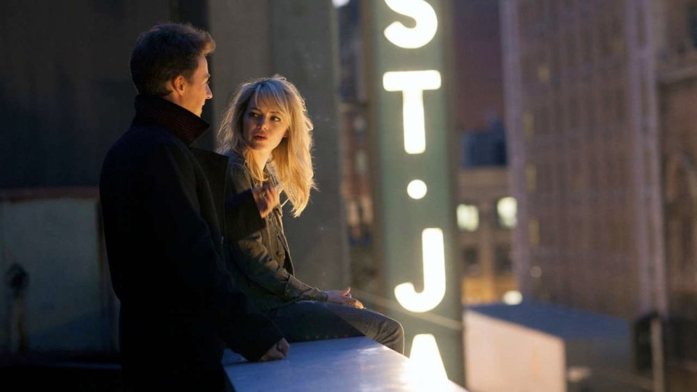
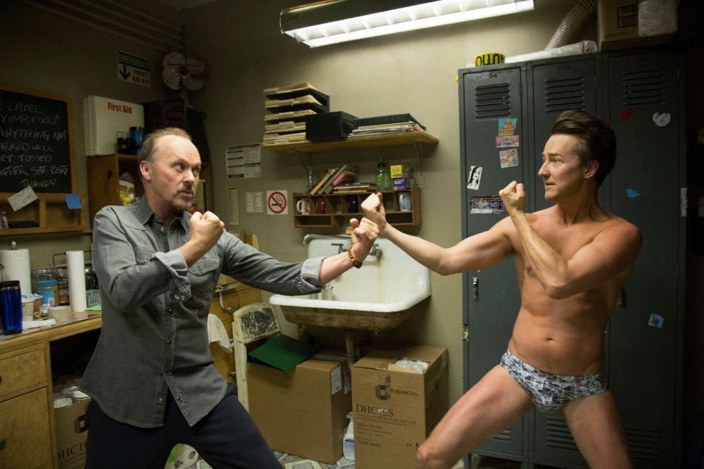
I would not pay too much attention to the exact direction of the light. As long as it comes from the left side, I think nobody will notice that you changed something between the two shots. Sometimes even within the frame, a practical lamp is put to justify some lighting, but if you analyse you can see that it is inconsistent. Two examples from "Birdman". In this shot, it's hard to explain how the light coming from the street could reach the interior of the hair and the ear of the girl (should be darken by her own hair). The bright "St. Ja..." sign also helps selling the lighting while it is actually behind the actors. Here again the neon is behind the actors, and should light their opposite side. One could argue there might be other ceiling lights, but the wall on the top left simply becomes darker as if the neon within the frame was the only light source. Moreover, in the real world, who hangs this type of lighting so close to a wall anyway ? In both cases, nothing looks fake at first sight.
-
How would you light it?
Nicolas POISSON replied to Ofri Margalit's topic in Lighting for Film & Video
You can light from both sides of the stage, together with honeycombs on the soft-boxes. The more on the sides, the less it spills on the background. But going too far you end up with the speaker's face dark in the centre, which is not pleasing (or very theatrical). So you need to keep the sources slightly on the front. Also, if the speaker is not at the centre of the stage, he will quickly receive much more light from the nearest side. Greater distance helps. Having the sources high above and pointing down also helps, because the shadow will be lower and less noticeable. And of course, the farther the speaker from the background, the better. -
Log curves and dynamic range of shoguns small HD
Nicolas POISSON replied to Abdul Rahman Jamous's topic in General Discussion
I did not investigate every single camera released recently, but I guess none of them has a strict Rec709 profile nowadays, as it would limit the DR to slightly more than 5 stops (if I understand correctly). I guess all current so-called rec709 profiles include some kind of "S-shape" tone mapping, or at least some highlight roll-off, because nobody would accept only 5 stops of DR, except for a specific project wanting to mimic vintage found footage style. Thus, the diagram in the first post exaggerates the benefit of log curves over SDR: In a 'IRE vs. stop" scale it would appear less impressive, and the "SDR" used as a reference is a norm nobody follows any longer. I went through the Shogun manual, and I am a bit confused with that chapter. It seems that this diagram has nothing to do with the way the shogun handles log signals or is able to turn into an HDR display. It is simply a representation of various vendors log curves, nothing more. -
Log curves and dynamic range of shoguns small HD
Nicolas POISSON replied to Abdul Rahman Jamous's topic in General Discussion
Imagine a mate white board that reflects a certain amount of the light it receives, sending it to your camera. You define this quantity to be 100%. You set the exposure of your SDR camera with pure Rec709 profile so that this white board reaches 100% IRE. Now changing the camera profile, it may be able to capture objects sending 4 times more light (400%), or 15 times more light (1500%) without clipping. In the real world, you may simulate this keeping the same board and just increasing the light source. This is a bit like estimating the variation of the cost of life through the years: you take the price of various products in 1990 and compute the total amount to be $1200. You define this as your 100% reference. Ten years later, the same products cost $1800. This represents 150% compared to 1990. The absolute values of $1200 and $1800 do not matter, only the ratio is of interest. -
This is the bandwidth of the SDI connection, expressed in gigabit per second. This limits the characteristics of the video signal you wish to transfer. Many factors are at play: resolution frame-rate bit depth chroma sub-sampling Typically, 3G-SDI will be used for FHD and 2K signals, while 12G will be used for UHD and 4K.
-
John P. Hess has made a video about normal lens. He focuses on the "typical image size seen from a typical distance" approach. Interestingly, he gives some figures about those typical sizes and distances, which translate into field of views ranging from 20 to 40°. For S35, this means focal length between 32 and 66mm. For full frame, this means focal length from 50 to 100mm. This illustrates how approximate this concept is.
-
A website (there must be many, many, many others): https://www.dofmaster.com/dofjs.html
-
Best all round on camera monitor?
Nicolas POISSON replied to Daniel O'Flaherty's topic in General Discussion
Hi, I came across this thread while trying to improve the accuracy of my Ninja V. Testing with patterns generated by a computer and HCFR software, the levels below 14 out of 255 on every channel are kind of clipped to black. This is not a problem of Legal/data range, as the Ninja is set to "data" in this case and the computer outputs full range. I was able to create a LUT using displaycal, that allows for these low levels to become viewable. The image gets closer to other calibrated monitors. The downside is that this LUT changes the waveform measurement, but I can switch the LUT ON/OFF. Also, I have to merge the "calibration LUT" with any other LUT I need to use (like LOG to 709 LUTs). Cumbersome, but doable. I was wondering: why does the factory calibration crushes the black on this device ? If the display lacks contrast, I prefer to look a slightly washed out picture with details in the shadows rather than a contrasty picture with crushed blacks. Isn't that what 1886 is all about ? Am I missing something ? -
Intra or Long GOP 1080P, and 25P/24P video questions
Nicolas POISSON replied to Jon O'Brien's topic in General Discussion
If the video is too be viewed on a computer or phone screen, it will be mostly displayed at 60Hz wherever in the world (although some phones have a 144Hz refresh rate now). The viewer's graphic card will do the frame-rate conversion, with the inherent risk of jerky motion. Technically 30 or 60Hz would be better for shooting, but billions users watch billions videos with various frame-rate every day, and nobody hardly complains. Many web videos are shot in 24P, even corporate ones that will never reach any theatrical release, just because that is the historical movie standard. For web, choose whatever frame rate you prefer, 25P is not better than 24P in 50Hz countries.