


Robert Hart
-
Posts
399 -
Joined
-
Last visited
Posts posted by Robert Hart
-
-
After managing to get the video larger on the screen and stopping the playback, it looks like that the clutch tension in the centred of the yoke is non-adjustable and there may be adjustment knobs in the centres of the white wheels themselves. The little felt pads on the yoke ends may be light brakes to stop rolls from unwinding or flywheeling the motion when the drive is not going to them. If there are not adjustment knobs then they may be fasteners and adjustment of tension may be by spacers or shims under springs like on tape recorders. It is too hard to know what the system is although if I had it in my paws I would work it out easily. That's it from me. Time to go to roost as it is very late.
-
Once you have adjusted the clutch tension, get hold of a full roll of junk film, load it and run it through to make sure it takes-up firmly all the way to the end but not too tight. You may have to mess around a few times to get it right and it may fall out of adjustment after a few rolls but after re-adjustment should be more stable thererafter. Good luck with it. The ARRI pin-registered transport is as good as it gets. Don't scrimp on getting the cam actuators and little helical gear serviced. If cameras sleep for six months, the lube goes off and needs cleaning then replacing.
-
I just got locked out again. further to the above. Before you go messing with the clutch tension, check those little felt pads to see if they have become shiny with contamination. If they have, you will feel them squeal under your fingers as you attempt to spin the white nylon wheel. Be very careful not to bed or pull on that yoke or you will ruin it. It will probably ne sufficient to clean them by wetting a piece of paper with isopropyl alcohol and easing the paper back and forth between the pad and the wheel in the same and reverse direction of the rotation. Don't try any adjustments until that alcohol has had a chance to dry off. If the felt has become polished and squealy, then the texture of the paper may roughen it up sufficiently. Do not try roughening the white wheel. You'll only bugger it up for good. Do not use any sort of abrasive to soften the felt. It will remain in the felt and ruin the polished surface of the white wheel. Be careful dressing the felt. It may pull off from the yoke if you apply pressure to the yoke. Just let it do its thing from the clutch tension pushing it not by adding pressure. It is does come off, you will find that toluene-based contact adhesive will re-attach it successfully. Just use a little smear on the felt and the metal tab and don't let it soak or press into the felt. Again, wait for better brains than mine to contribute, preferably from the ARRI service manual.
-
Furthur to the above, I had a look at your video and I think I understand the clutch system. It is similar to that of old tape reel-to-reel tape recorders, old analogue and early pre-servo drive digital video cameras.
The amount of pressure upon those little felt brake pads which push against the nylon wheels appears to be determined by a common clutch on the rocking yoke. There appears to be a diaphragm spring with spokes at the pivot point of that rocking yoke. It is too hard for me to see in your video on my computer but my bet is on there being an adjustment screw in the centre of that rocking yoke's spoked diaphragm spring. Clever ARRI because it is a system which historically has been very reliable. That diaphragm spring likely has a friction disk beneath it.
Now this is where it will get tricky. ARRI servicemen probably used a tension gauge to measure the resistance of that clutch. If you go taking it all apart without counting rotations of an adjustment screw or whatever, you could be on a ride to the hell of frustration.There may be a very narrow margin between too loose and too tight. If you can, get somebody to video your adjustment efforts so you can return to go. The clutch may be gummy and incapable of adjustment to a consistent tension.
If you are lucky, then backing off the tension in quarter turn increments may get you what you want.
-
Something went pearshaped when editing the previous response so here is another try.
The ARRI is very likely different however in loading your magazines, it is possible for the film to pass on the wrong side of an outfeeding roller. This can happen with a CP16 magazine's light trap roller. The CP16 camera will tolerate it but also may scratch the film.
I observed that you were dragging on the film to action the camera motion. You will damage the film as the gearing becomes an increase drive. It is a reduction drive when powered by the camera motor. If the film is walking off the side of a sprocket then what may be happening is the sprocket itself bending off-axis due to an overload.
The bend may not be in the sprocket shaft or its bearings although if they are worn, then this is possible. there may be flexing of the magazine's structure under an overload state which forces the sprocket shaft off-axis. If that is happening, what then is causing that overload state?
Is the film passing on the wrong side of a roller of sprocket?
Is the film loop within the camera too short and pulling up tight on the infeed or outfeed sprockets, imposijng an overload, bending the sprocket/shaft/magazine case off axis and walking off?
Are the clutches on the magazine spool axles adjusted too tight or have become contaminated with oil and become grabby? - I am assuming that the ARRI magazines use a clutch on the take-up spool axle or underneath a driven gear.
There may also be a clutch on the in-feed spool axle it the driven gear if the camera is capable of reveerse operation.
While the rotational speed of the transport sprockets remains constant with the camera speed, the take-up spool must rotate at varying speed to compensate for the roll of film becoming wider and by necessity must turn increasingly slower.
In the CP16, the magazine is driven by two belts, one an elastic belt which can slip before film is broken and another cogbelt. In the event of a lockup, the worst that can happen is to wipe the little teeth off the cogbelt.
The ARRI has a gear system which will not so easily forgive an overtight or jammed clutch. It will bog and eventually ruin the electric motor. The narrow magazine gears may warp and skip teeth which will ruin them soon enough.
I have no idea how the film tension is adjusted with the clutches on the ARRI. As I mentioned above, they may be on the magazine's spool axles or may be inside or behind the driven gears.
If they are on the axles like the CP16, then the adjustment will be a threaded nut or wheel on the axle shaft, which pulls a flat disk down onto a short coiled spring which pushes against a clutch plate. The clutch plate may be free-sliding on the shaft with a key or spline to rotate it or a diaphragm spring which does the same job s the coil spring and plate. It will look like a really skinny wide washer and may have holes or spokes in it.
In both systems, the threaded wheel or nut will be secured by a small grub screw which binds it to the axle shaft and hold the adjustment until wear makes another adjustment necessary. The friction material ay be a thin phenolic disk or felt. If contaminated by oil wicking out from the shaft bearing, the phenolic disk will simply slip easier and lose tension. The felt disk may become skippy, alternately slipping then gripping hard. This will affect the speed stability and in extreme conditions may cause varying exposure of the film as the transport stutters.
Depending upon the direction of rotation and thread being either clockwise or anticlockwise, if that grub screw loosens, the clutch adjustment may self-tighten or self-loosen. If the clutch self-loosens, the take-up spool will stop winding the film which will gather up inside the camera and jam. If it self-tightens, then the tension on the film will increase and loading on the geardriven sprocket will increase and cause the issues you are having.
If the clutch tension is to strong, then the film will wind on very tight and may cinch the emulsion causing short vertical scratches. If the wind is too loose, then it will fall apart like a roll of toilet paper off the plastic core when you try to extract the roll and send you insane trying to wind it back on.Knowing just how particular ARRI was with precison engineering and how well thought out the film drive itself is, there may be user-adjustable knobs on the centres of the take-up and infeed centres on the outside of the magazine to fine tune the clutch adjustments. However I am really only guessing here.
Wait for better brains than mine to contribute advice based on the actual service manual for the camera. -
The ARRI is very likely different however in loading your magazines, it is possible for the film to pass on the wrong side of an outfeeding roller. This can happen with a CP16 magazine's light trap roller. The CP16 camera will tolerate it but also may scratch the film.
-
For going the other way, the 81EF filter is a less aggressive colour correction for using tungsten-balanced stock in daylight. In early evening, using this filter with tungsten-balanced film confers a sweet look to the evening sky as background.
-
 1
1
-
-
Choosing a film of the wrong colour temperature will not help in regard to visual effects. You are really only changing the hue of the recovered image. Your visual effects will be better achieved by lighting and production design. Before you go burning off a bunch of expensive film, maybe do some tests with a digital stills camera with varying colour temperature settings. If you are stuck with daylight film already, buy or hire an 80A colour correction filter to fit to your camera lens or slide into a mattebox. You may lose two stops of light. You could put blue gel over your tungsten lights but you would also lose about two stops worth of light. Grading film images which have not had a colour correction filter in front of the lens may be a bigger ask of your colourist. If the majority of your shoot is to be nights under tungsten light then you should choose tungsten-balanced film which will require less light for the same exposure than blue gelled lighting to daylight film will yield. That is the whole reason for tungsten-balanced film. For the fewer daylight shots, then use Type 85 filters for the tungsten-balanced film. Loss of light due to the filter is less critical in daylight conditions. Take greater heed of better practitioners than I who may add comments here.
-
Surface coating films can cause difficulties. At a cinema in a remote town, I received a 35mm print of "Rocking Horse Winners". As a second-tier cinema we received the prints after they had done their time in the city cinemas. The print looked good with no scratches or signature scuffmarks of being fed off a platter system but went only through part of the first reel before it began to bind in the gate. Whatever was used to rehabiitate the print was coming off, cooking onto the gate and pressure plate and frying on hard and sticky. It was so bad that it stripped the holes then bent the pulldown sprocket off axis and walked off the sprocket. We had to abandon that reel. The next reel behaved just the same. It fouled both projectors for the night and the screening was over. It might have been okay on a Cinemeccanica with a "cold light" lamp system but with our carbon arcs on old C&Ws, the gate was probably too hot. To get a good throw onto a large outdooor screen we had to overdrive the arcs. Beautiful pure light came out of those things.
-
I see nothing wrong with doing this but I am also an unqualified mug. Once you establish with tests that the results are good, it will save you having to scramble around with the handheld meter.
-
He using fancy words which is what people do on lecture circuits and events.
The work to change a good script into film must also be good or the audience will not enjoy what it sees and hears. -
For what it is worth, in this clip there are 8mm, 9.5mm, 12mm, 16mm, 25mm, 50mm, Optar Illuminas, 20mm, 35mm, 85mm Optika Elites. It is not a proper technical test. There are more accomplished folk who can do that far better than myself. The camera was a SI2K. The lens apertures were set at T4, close to their sweet spot of around T2.8 if my geriatric memory serves. The image seems to be consistent across the two types which are descendants of Lomo lens designs. A DoP friend prefers the look and clarity of CP ULTRA T* primes by Kowa. They seem to be warmer than the Optar/Optika lenses and yield higher sharpness numbers on the SI2K from a Lemac chart. The available range was 9mm, 12.5mm, 16mm, 25mm. The 9mm does not cover Super16mm unless modified. It also has a peculiar two stage focus system which has a noticeable change of pace during the focus movement. I had two sets for 3D with two SI2K heads. Some of them had an image shift issue which was more observable in the longer focal lengths. The image "walks" in a circular orbit with focus movements. The focus mechanism is simple except for the 9mm. The front of the lens block is threaded and the entire lens block moves. The tail of the lens block apparently may float a little. Maintenance and damping the tail with suitable lubricant apparently reduces this issue. One of the Optars jumps with reversal of focus movement.
-
Charles.
Thank you for the information and link. -
Slightly offtopic. Would latent images on German WW2 1941 35mm motion picture film be recoverable? The storage environment would have been original can sealed with oilcloth and tar against saltwater splash. Can buried in limestone soil for 70 years in seasonal temperatures ranging from 5 degrees C to 38 degrees C with hopefully more even temperatures through being buried. This information is for a screenplay project. There is a remote chance that a roll of 35mm motion film in a can and a roll of 35mm still film in a Leica camera body still exist, buried in a hollow in a steep limestone face. Wartime searches for the camera and film were unsuccessful.
-
This is a screenplay research question. Somebody might have an answer or two. If an oilskin and tar-covered can of German WW2 unprocessed Agfa 35mm motion picture camera film was stashed and buried in a small deep hollow in layerform limestone where ambient air temps range from about 5 degrees C at coldest to 40 degrees C warmest, could the latent image have survived? The processing chemistry is likely not known any longer or possible to replicate. How would a person requested to process the film go about the task with any hope of recovering a usable image? There might also be the question of whether the film stock was the older nitrate based material which would have turned to powder or a more modern acetate. Whilst the story is fiction, there is a remote chance that there remains stashed, a Leica stills camera with an exposed roll in it and a recanned 100ft load from an ARRI 35mm motion picture camera on the Western Australian coast north of Carnarvon.
-
The Foxtel dishes like the one in the image above are a cropped offset parabolic shape and work reasonably well as a parabolic mic. Where the satellite pick up is I fitted in the hollow, a plug of black foam with a small hole in it to support a Sony lavalier mic. I have not done comparative testing with a shotgun mic. I have tried a huge 1.5M spun aluminium dish. It worked well but is totally impractical and becomes a huge rumbling sail in any breeze.
-
Ken Hale at Whitehouse AV is still active and vending parts for the CP16 camera family. Paul Hillman who was at Whitehouse AV when I visited through there in 1996 is now at Visual Products. He is the guru for converting CP16Rs to PL-Mount and Super16mm. I saw his first one at Whitehouse AV and had the opportunity in that visit to compare the methods. Mine was to open the existing gate, remake the rollers and remake the tails of the lenses with an offset to move the optical axis to the Super16 frame centre. His arrangement was the more thorough option of moving the film path to retain the existing optical center.
-
There appears to have been several revisions of the PCB and components. This diagram is of a version "B" and the PCB in my camera is a version "E".
That might be a bad guess on my part as I do not understand the diagrams. The PCB in my camera appears to have been patched with wire bridges due to corrosion from a previous battery spill.
I wonder if modern ELNA supercapacitors as used in Blackmagic URSA cameras would do the job for the average life in camera of a 400' film roll. -
Here is a picture-phone image of a page from the service notes I was lucky enough to have been given with the camera.The notes are not relevent to the BBC shutter version but to the bowtie shutter version.
Chance may be that the diagram has been created from the original PCB mask artwork which if scaled to size in photoshop may be accurate. For making a new PCB, the artwork would have to be reversed and component layout "white-inked out" with whatever tools photoshop uses to do that. The trace layout is as if viewed from the right side of the camera.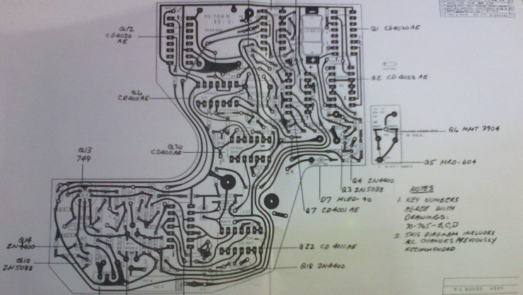
-
In regard scanning boards. I think there may be outline diagrams in the full service manual, which could be used to scan scale down and make a mask to etch a new PCB.
In regard making a new tacho circuit/motor controller from scratch, there is reference in the maintenance manual to a diode which is across the motor to prevent inductances harming the audio amplifier. That may have some effect on new design work.
The manual suggests that the camera requires servicing every 12 months used or not. The cameras in Australia that I know about were required to be serviced every six months. There is reference to a special lubricant. Likely this will be for oilite bearings which are plain bronze bearings, not ball or roller anti-friction bearings.
The wrong oil may clog the sintered bronze which enables the storage of lubricant within the bearing material versus it being squeezed out to wastage within a a short period of operation. -
You may find that the little hatch on the top of the camera has become glued in by magnesuim corrosion and a gasket underneath. YOu may find a 1/3"CCD security camera and 25mm C-mount lens with one or more plastic CS-Mount to C-Mount spacers will do the job for you. You may need to get a semitransparent mirror piece to replace the viewfinder relay mirror inside the camera body.
-
Whitehouse AV in Southern California and Visual Products in Ohio were the go to places for CP16 maintenance and repairs.
There are two paths of drive to the take-up spool in the magazine. One is an external belt which runs fro a pulley on the camera body to a pulley on the magazine. That belt is a simple neoprene ring and could possibly be found as an o-ring seal. Another is a ladder cogbelt which is inside the camera body. This belt is more problematic. It is a one-off for the camera type.
It appears to be moulded rubber around a cord core. The material ages and perishes. The cog teeth fall off, dropping to the main gear and lodge between the drive gear and the driven gear. If it does not lock the drive entirely it may embed between two teeth and cause lighter frames as it cycles though and momentarily baulks the shutter drive.
There are belts kits advertised by Whitehouse AV on eBay as mentioned above. The new ladder belts appear to be a synthetic material and longer lasting. The cogbelt is essential for accurate counting of the footage run through the camera. If accurate numbers on the footage counter are not a consideration, you could probably get away with using a toothless o-ring belt. -
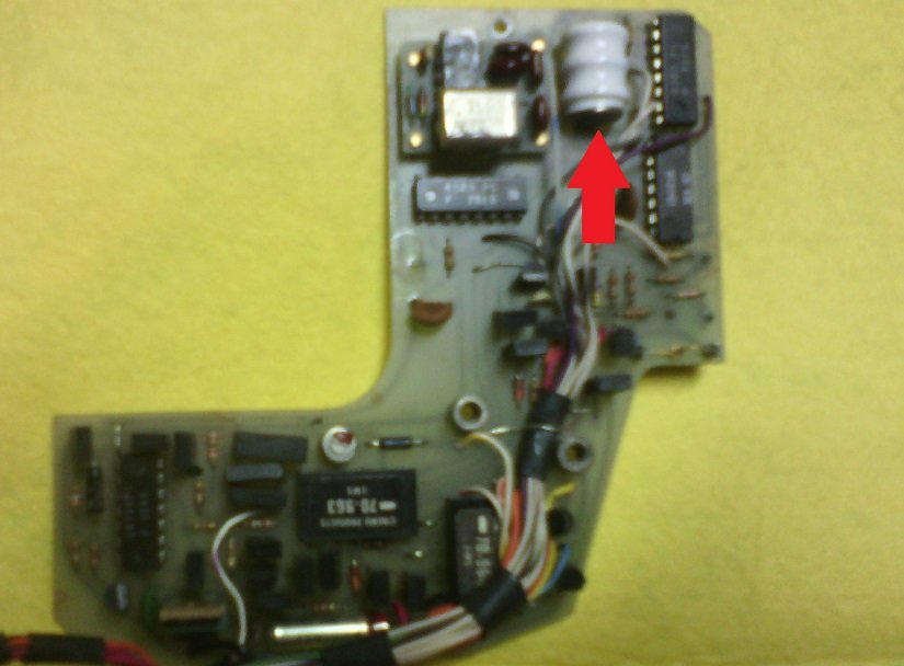
The battery fits into a hole in the PCB with the solder tags on the reverse face. The leak is a blue crystalline deposit which works its way down the board and spreads out. The optical interrupt for the parking function is one item ruined.
-
If you have confidence to buy something from Sri Lanka, there is a CP16R bowtie which is missing some parts but has what looks like a B4-Mount video tap fitted with a small optic inside. However a B4-Mount also looks very similar to a CP-Mount so the videotap viceo camera may have been unique to Cinema Products and using the CP-Mount. For a 1/3" CCD security camera, I have a vague idea the 25mm C-Mount lens with an extra few C-Mount Spacers may do the job for you. For a home-made telecine on a 16mm Steebeck using a 2/3" sensor camera I had to use a 50mm C-Mount lens with several C-Mount spacers. The lens is a Fujian, very affordable from China. The range also includes a 25mm and 35mm. Just be careful when mounting or dismounting this lens. It is easy to overtorque the lens in the mount and then accidentally unscrew the front out of the lens. Also take care not to apply torque to the iris ring at its end stops if trying to unsccrew the lens fro its mount. The mechanism inside could become damaged.
https://www.ebay.com/itm/Cinema-Products-CP-16-Camera-body-magazine-View-Finder-is-missing-Sell-as-is/324368480749?_trkparms=ispr%3D1&hash=item4b85de39ed:g:FAAAAOSwOA5fql0x&amdata=enc%3AAQAFAAACcBaobrjLl8XobRIiIML1V4Imu%2Fn%2BzU5L90Z278x5ickk5v8gVt3hEWLVg%2F253w6XCcrs2aG7hG3m%2BL4gX5z5XJ4jeNV6QUft6LMYhzaviPZeY8MzmFiExqjmORE3sSzEYgZfVOOkGZzl1nJTFyCNjyMOhkuk0un6mZbmeOfjQD5wnMcEmMoBk%2Bm3LzNolR3%2FMAy7s8aMfWfDrdZbU4%2BNlTpUNKjmCjXo0%2FJTmmh2T2dXK%2FBFTSDtOxi0jXtXXcLHV%2Bzgsx%2FEROI4oPQtwX6WwR%2BfpRNHqrY9W5kIdrGM0uSuXHfWddmVJq4DIDHlgKZS6v%2FsoptwoDGbbbzMQBWeO6QG827rnU%2BV%2BeA1gqpkj%2BeYbggke4ytstHu73tPye1QhcCRZ8mnRWmNWuH%2Fq32BDQgRlvOGP3PJ%2BMsd37NFAtb7xNrxoOHO3v2%2BbAC%2BkaoU9wnbFbXFY440ZZlMmd3oh9AgQR5VYHWd9vgFBjSSGWKO8O7Z2f%2Ba2ee1wJv5x5TI5GYGNT%2Fj5HJShdqRpFOqSxGjLMBHiZDXBFKUE3w70%2Bg33qU0%2FfjnxKThkwRwRNALyKYoqCWFKtVafw3%2BOb1yapO8ga%2B%2BisyiGtEbbzTuEEQVd4r8HQDJ4cANtRyCZOsYurWcsjsppBaH43XijZcY3iOjWl%2FQ6ZfA75jwkDj3Y3y4L6qtbYR5Y8jxHLyTBmHrbklGSbnc0OAj9vFDKvYU9g6kF2m3%2FneWPCYnnJ7vxBA1mvKUV1L7MBYBeJvhN%2F4AibzIQHdRvrr6qD3cYV%2FDcXEC0As4d8OALDoDXZn5xWlRCUI6UKFuqFpwfJCUmdsotA%3D%3D|cksum%3A32436848074904e2cd235c284a59800dc7d4c087dbd6|ampid%3APL_CLK|clp%3A2334524#viTabs_0
Arriflex 16BL Problem, Why do both cameras do this
in 16mm
Posted
A good outcome then. I hope I did not send you off on dead-ends with the first few responses.