Pol Fieldman
-
Posts
7 -
Joined
-
Last visited
-
Hi Baltasar, A year ago I set out on a similar quest. It took me about 400 hours before I could start transferring movies. If you are not familiar with electronics, mechanics and programming you should be prepared for an even longer journey. I’ll try to answer (part) of your questions from my own experiences (for what it is worth …) 1. for me the core decision is which camera to use, and how to get the images to the PC. Depending on that choice you will need different skills to complete the project. Important properties like resolution, image dynamic range, gain control , white balance and who is the master ( who decides when a picture is taken : the camera or the projector ) are fixed with these choices. The simplest solution I’ve seen so far is to use a standard video camera to capture at near full speed and use software to drop duplicate frames. This way you do not need to replace the motor, capturing is trivial and post processing can (probably) be done with off-the-shelf software. Or you can use an Arduino board: use the camera, drive motor and store images. You should read about different possible solutions and decide what is important for you. After reading a lot and experimenting with webcams, my personal conclusion was that dynamic range of the image capture (number of bits available at the camera) was very important to get the most out of the movies I have. So I chose a 12bit machine vision camera. As a consequence I had to write my own capture software. This gave me full control of the camera at the expense of a lot of code writing. 2. Motor drive: some solutions can keep the existing drive system running near full speed, others use DC or stepper motors to do slow frame movement. I used a stepper motor (and made my own drive hardware) because I had a stepper motor lying around. If you use a DC motor, the speed control is not as precise but driving a DC motor is much easier. 3. Lighting system: Unless you run at normal speed and have a good IR filter, the lighting system should be replaced by a cooler light source. This can be rather tricky as three things should match to get best results: spectrum of light source, spectral sensitivity of film grain and camera. Classic options: separate rgb leds or white led. 4. Mechanical setup: removing unnecessary projector components, and very important: a stable and precise mounting of camera & lens. Fine positioning and precise alignment (parallel to film) is critical to get the best out of the camera. 5. Post-processing of the images, turn them into a movie. This is one of the easier steps , as good free software is available to do this (Eg. Avisynth.) And of course you should be prepared to encounter all sorts of problems, e.g. some of the problems I had: - Even with a near perfect light source I got very uneven lighting on multiple webcams. Never really understood the problem, it went away when I used the machine vision camera. - Reduced sharpness near edges, caused by imperfect alignment and too shallow depth of field of lens. - Green led that emitted too much blue light. Had to select another green led. - Problems with mechanical transfer of movie through projector ( image jumped to much between frames) - (my own capture software) : Writing images to disk sometimes took too long, solved by saving images asynchronously . - Very large quality differences in recorded movies. Sometimes extreme under exposed film, requiring a much longer shutter time. - Finding a good algorithm to regulate camera exposure. In my case the light output of the leds is constant, and I changed the shutter time. You can also regulate the light output and keep shutter time constant, or go for manual adjustment of the shutter or light level. My advice would be to keep reading and experimenting with simple things (like a webcam) to get a bit more feeling of what is needed. I wish you a lot of fun with this project, Pol
-
Hi Ian, I understand and like the concept where you remove the rotor/gate, video the frames including some blurred fields, and filter out the usefull frames with software. The thing I was worried about a couple of months ago was the effect on the image quality of having two lenses in the optical path (the projector lens and the camera lens). But I didn't try so the effect could be neglectable of course. This does not effect the beauty of the above concept, it works just as well with one or two lenses in the optical path. Pol
-
Hi Ian, Sounds like a simple approach that allows you to get near realtime transfers and good quality results. When I was weighing my options, I came across this idea (problably your post at doom9...). I didn’t look into it further, because I didn’t understand how the image projection worked. ( I should of asked you back then, it could of made things easier for me...) Do you have two lenses in the system ( one magnifier, and the camera’s lens) or do you remove the camera’s lens ? In my setup I use a stepper motor because I had one lying around, and wanted to run the projector slower than it was capable of. A brushed DC motor with suitable reduction would also of have been good (and easier to drive electronically) Because the projector is the master of the system, it can run at any speed it wants. Each time the frame is stable the reed relay sends a signal to the PC to capture an image. The only constraint is that the PC should be able to capture and store the image before a new trigger is received. I use a Sanyo Denki 2-phase stepper motor (103H546-0440), that is driven by a JRC NJM3772 stepper motor driver. This is actually a microstepping driver, but I use it with a fixed voltage on the VR pins. The electronics work like this: · A sawtooth generator (two opamps) produces a variabele frequency. (using the original projector speed potentiometer). The generator has a softstart function to avoid loosing stepper sync. · This signal is fed in a 4040 binary counter. · Using XOR ports two outputs of this 4040 are combined to form two 90° shifted square waves. · These square waves are fed to the phase inputs of the stepper motor driver IC. Using an off the shelf stepper or DC motor driver would make things a lot easier I guess … but not as fun... Have a lot of fun with your project and let us known how it is going. Pol
-
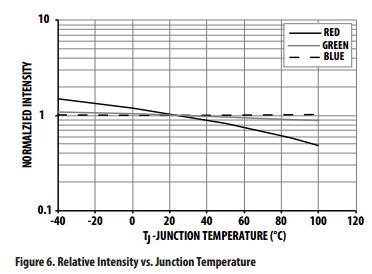
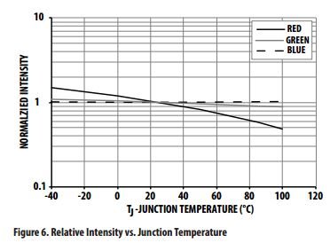
@Josh : My father bought the Sankyo projector back in the 70s. It worked fine without problems. In its stripped form it also works fine : reliable film transfer & windup, good access to film gate & easy to clean. You should really continue your work, it's very satisfying once you get to see results. @Phil Correct, LEDs have a significant negative temperature coefficient. Even worse, the red led temperature coefficient is significantly higher than the blue and green led. e.g. : from a datasheet of a typical low power rgb led. Since the total led power dissipation in my leds is low, and they are mounted on an aluminium baseplate, the effect is minimal. Some measurements : t=0 -> r=g=b=100% brightness ( rgb switched on after being off for long time) t=5 min -> r=97% , g=b=99% t=15 min ->r=97% , g=b=99% So the effects are very small, certainly if you wait a few minutes after switching the leds on. Pol
-
These are the c# source files I made for my telecine project. Please note I am a complete c# novice so don't except clean code.. But it works ! Suggestions to improve my skills are welcome... It was written in Visual studio community 2015, and you problably need to install the Microsoft.Tpl.Dataflow.4.5.14 package. TelecineV1_PFI.zip
-
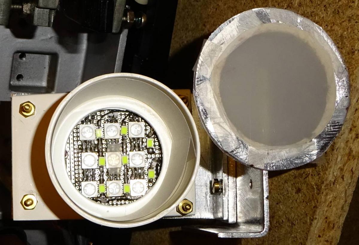
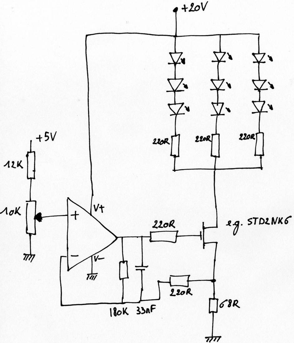
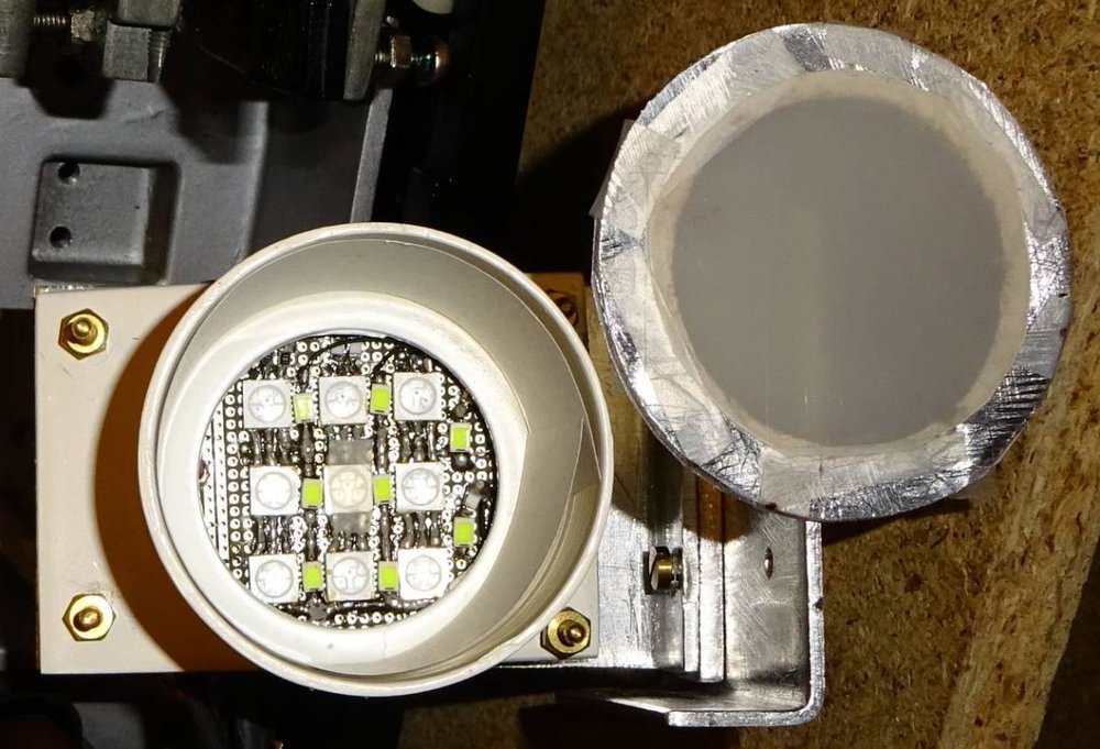
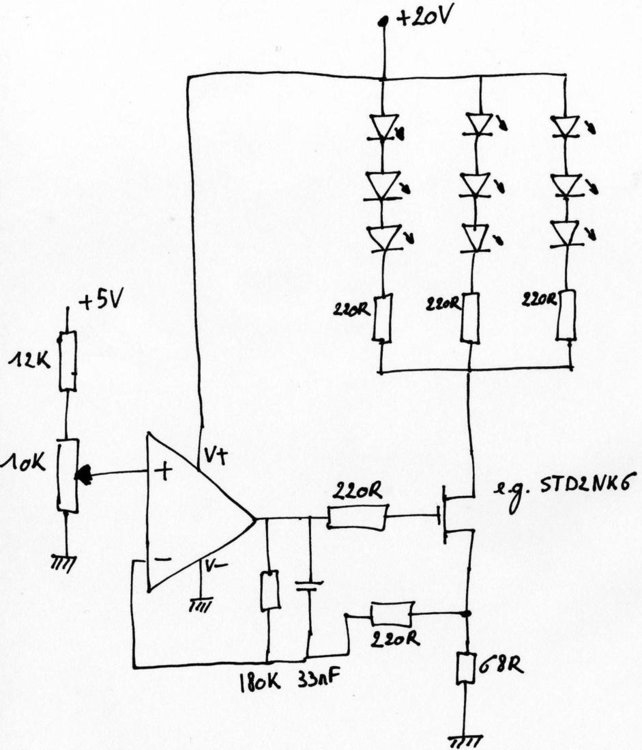
@Phil : No experience with negatives, I only got "projectable" reels from my father and grandfather. @Simon : Thanks, I had a fun time building it. About the LED light source: I started with taking 9 RGB leds from a rgb ledstrip I had. I soldered them onto a small PCB. The results were disappointing, because the wavelength of the green led was way too close to the blue led, resulting in poor color rendering. (the light source, film die and ccd bayer filters characteristics need to match ). I ordered separate green leds ( 545nm) and used these instead of the rgb green led. The result is much better. I use a basic current source to dim the light. See schematic for a single color. I did not use PWM because I was worried it could cause flickering. (if you use 1KHz PWM frequency the led flashes once every ms. If the exposure time is say 10ms, the ccd sensor can receive 9 or 10 pulses. Which would give a 10% difference in luminance frame to frame.) Getting an uniform lighting of the film was a bit of a struggle, but the method I use now works fine. The light is mixed and reflected in the white tube, and the frontcover contains two layers of light diffuser foil, recovered from a lcd backlight. To be really honest, I also tested with a halogen light with a good IR filter (to avoid burning the film and avoid flooding the ccd), and this also gave very good results. A halogen light is easier and requires no electronics. The disadvantage is of course that the blue ccd pixels do not receive as much light as the red and green, causing some loss of dynamic range. But in my case the loss was approx. 30% ( white in the film is detected as red=100%,green=100%, blue = 70%), which is not that much considering the 12bit dynamic range of the sensor. The real advantage of leds lies in the ability to supply very short and intense light burst, ideal if you want to keep the exposure time very short. For my 3 frames/s prototype not needed. Pol
-
Just finished capturing about 40 reels of normal8 and super8 film with my diy telecine device. I could not have done it without some great tips on this forum. Thanx all! some technical details and samples :