Duncan Brown
-
Posts
497 -
Joined
-
Last visited
Everything posted by Duncan Brown
-
Eclair Flea Market
Duncan Brown replied to Gregg MacPherson's topic in Marketplace Listings Under $200 / €200
It doesn't swing completely straight out to the side, so it's a little tighter and clumsier for left eye viewing than that special purpose extended one. Duncan -
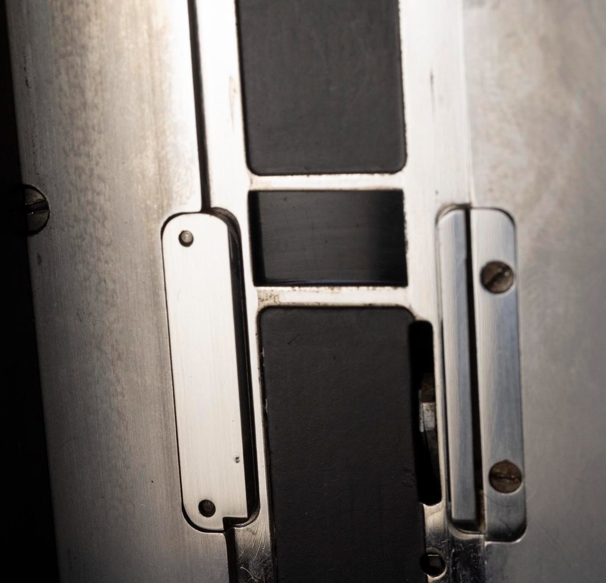
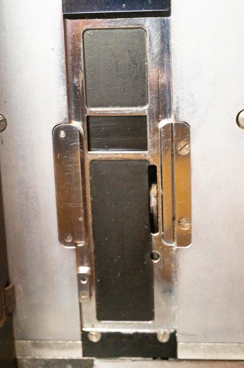
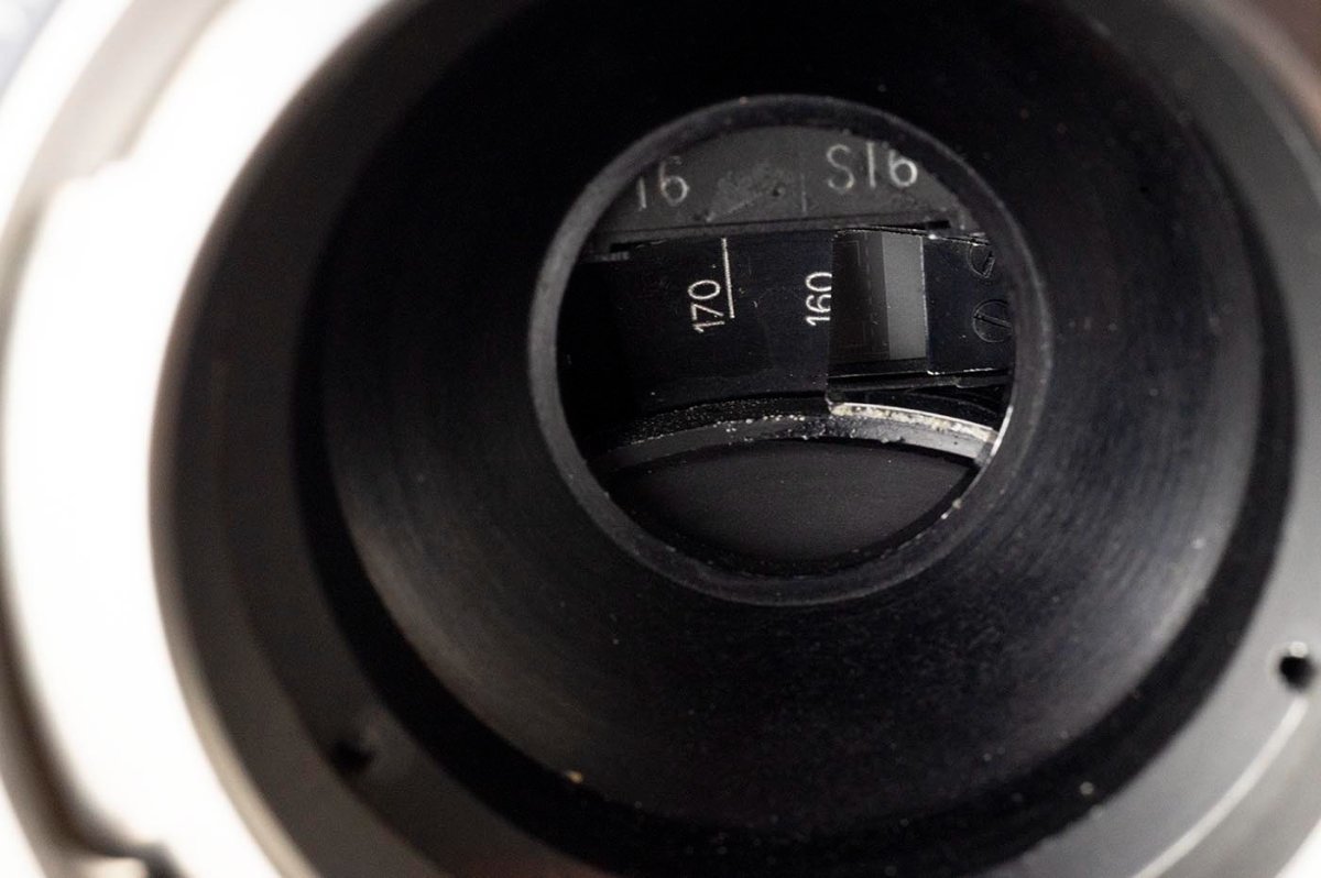
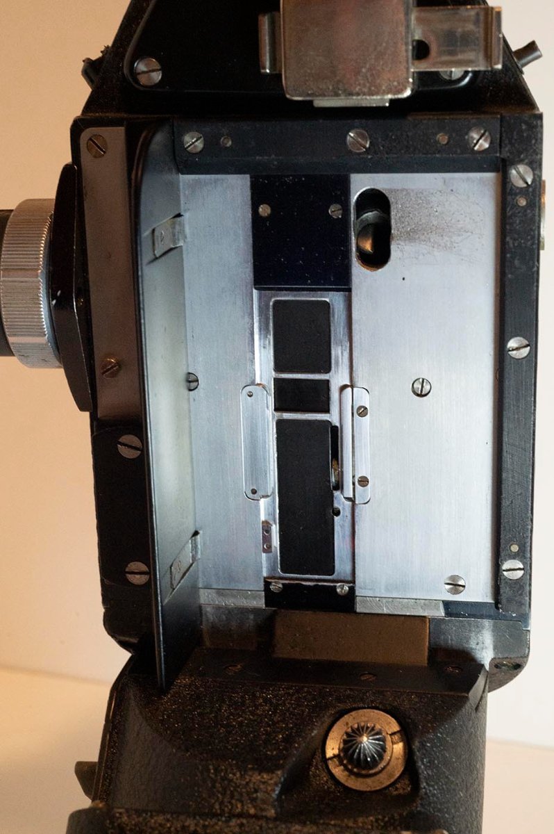
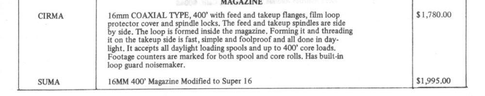
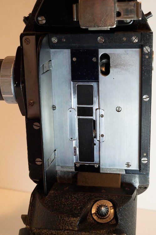
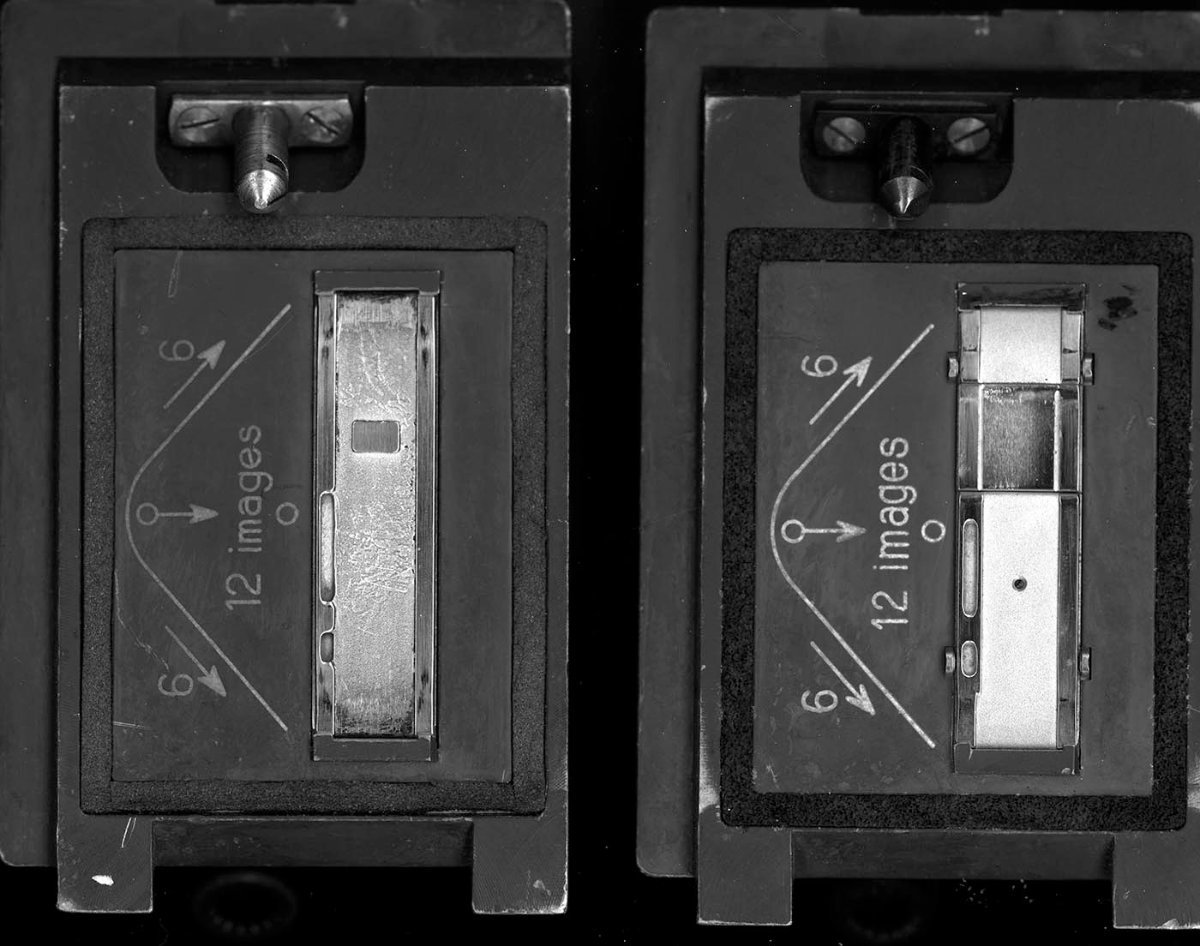
I'll eventually put more pictures and words here as I investigate the mags I've got and how to get them in better shape, etc. But I thought I'd start with a simple (?) question. What is the meaaning of the difference between the pressure plates on the two mags pictured? Just different design evolutions? (I have two like on the left with serial numbers that start with "A" and two like on the right with serial numbers that start with "B" if that is a clue?) Or is one of them the "Super 16 modified" version like mentioned in the 1974 price list I've included an excerpt of here? Duncan

-
Eclair Flea Market
Duncan Brown replied to Gregg MacPherson's topic in Marketplace Listings Under $200 / €200
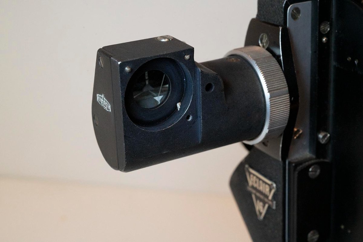
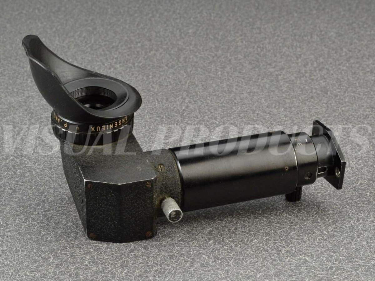
Visual Products has an interesting "left eye extension" viewfinder for the ACL by Angenieux on ebay. I won't put a link because two months from now when it stops working everyone who reads this thread afterwards will be frustrated by that fact. I'll post a couple of their pictures here - go search for it if you're interested in buying it ($535 USD buy it now). I'd also be interested in any comments on this item, since I'd never heard of such a thing before. Was it designed for a different camera? A one-off for a left-eyed DOP? Duncan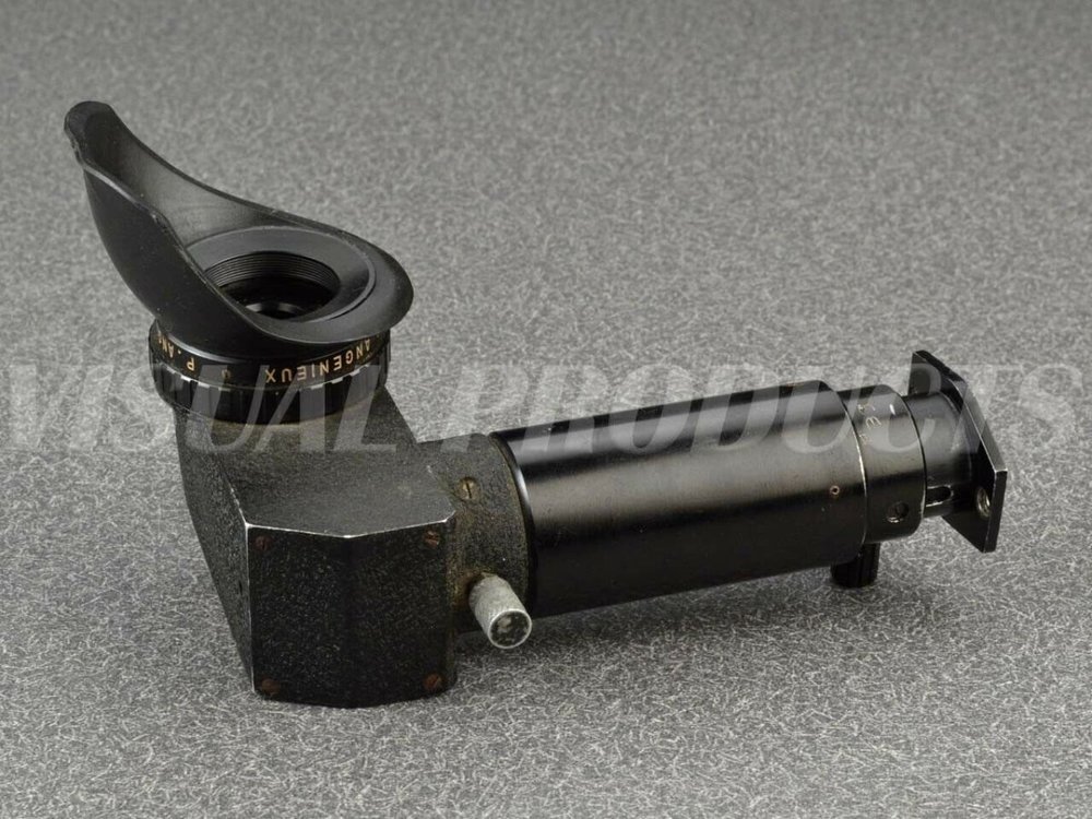
.thumb.jpg.77a262b007c655b7b12432f425449223.jpg)
-
My chips are missing in transit. Working with the seller to find them or send new ones. In case you were waiting with bated breath for the next installment of this saga... Duncan
-
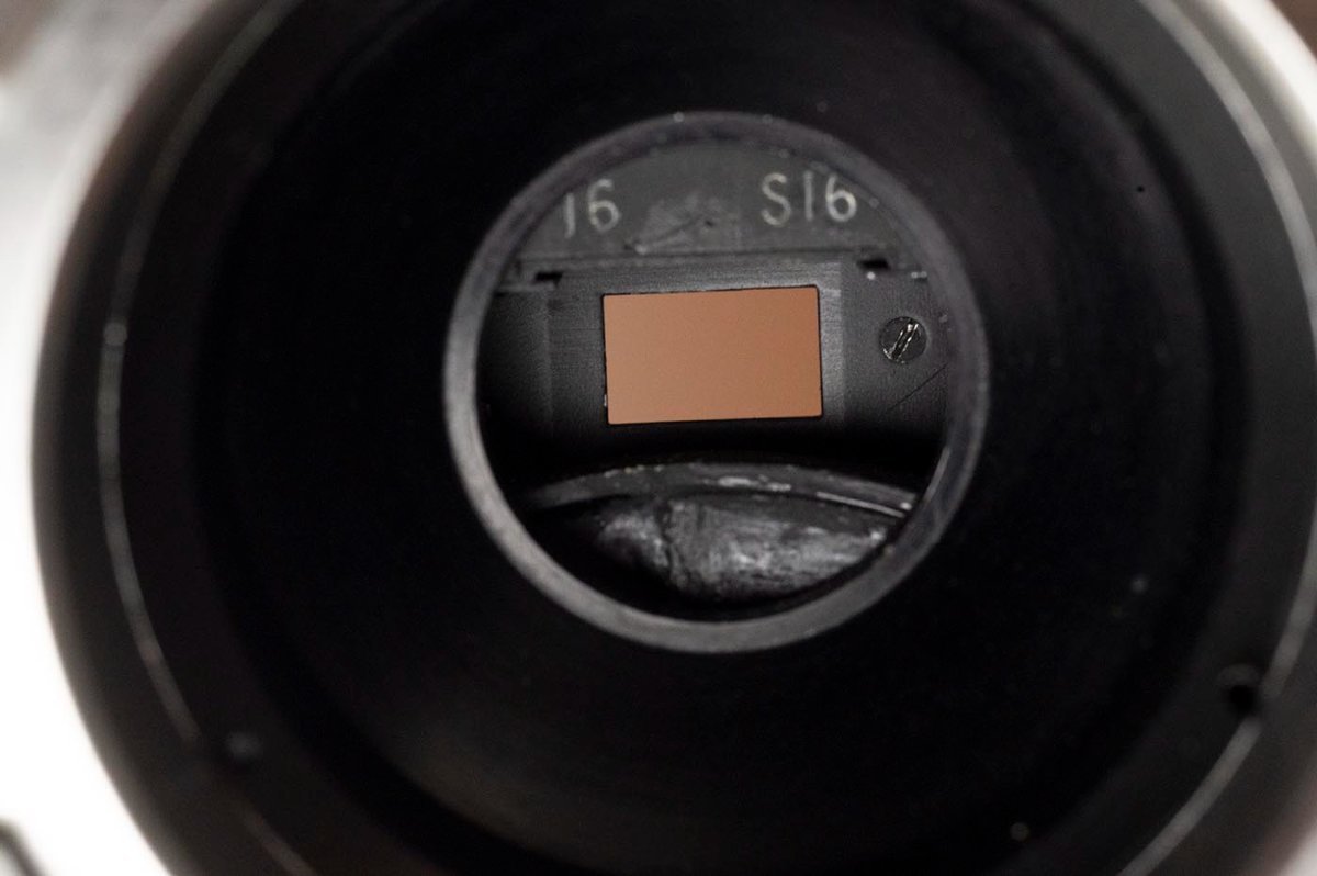
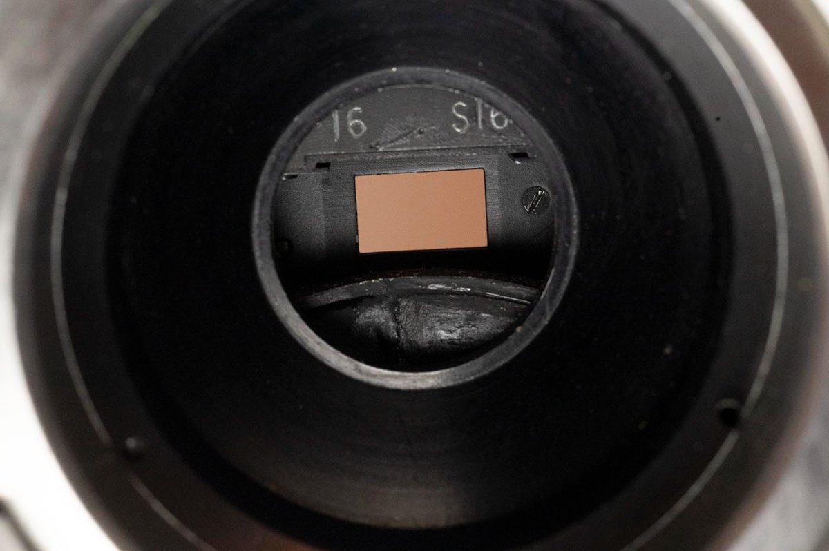
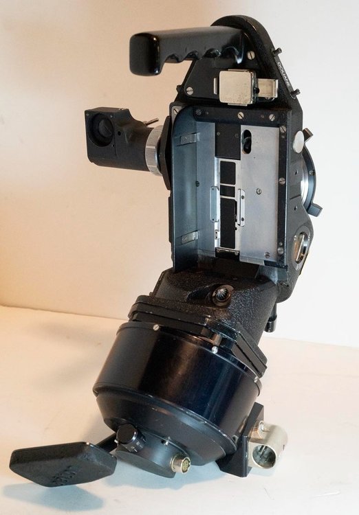
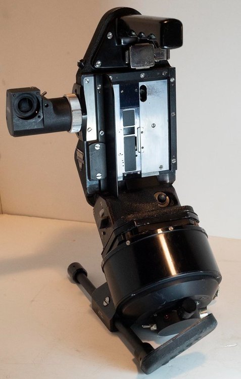
The perfs don't run across the gate on the right side, of course - they're over where the claw is. But on the left side, I see a little wear patch, more obvious on the bottom side, but also there on the top, that corresponds with where the perfs are, to my eye. On most S16 cameras you wouldn't see that, because you'd only ever run single perf film through it. But this convertible camera, especially if it really were a rental, would have double-perf film run through it back in the days when that was plentiful. The aperture looks to be even, and to have been made as S16 width from the get-go, another reason I think it's the factory option. That motor is AMAZING, even without being able to bionically click into your shoulder. It's very light. The camera doesn't lurch forward if set down carelessly. The trigger switch is well placed. I need to weigh it in comparison to the stock Perfectone motor, but it is very noticeably lighter when lifting the camera. Duncan
-
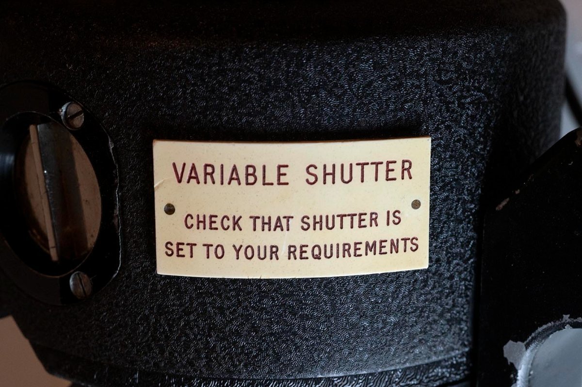
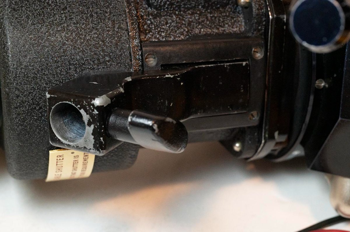
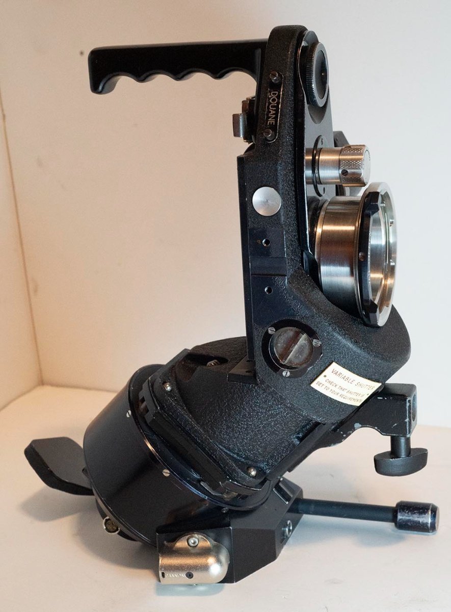
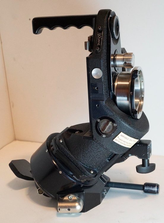
I'm also guessing it lived its life as a rental camera? The shutter angle warning plate would make more sense in that setting. Duncan
-
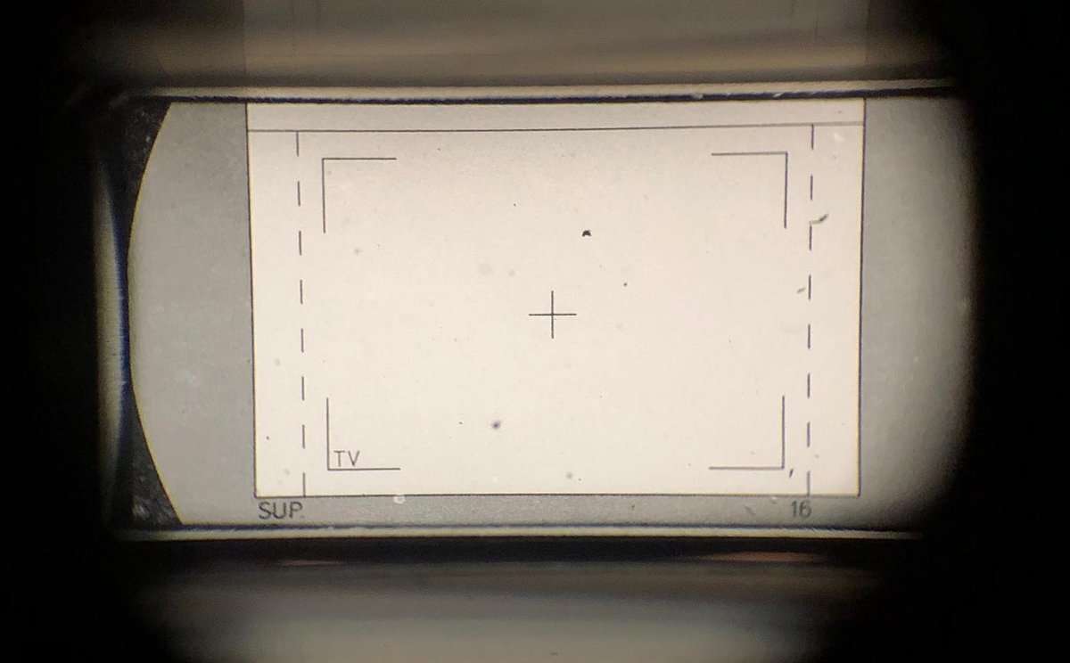
Yes, it came with half a Kinoptic finder. If someone has the front half to a Kinoptic finder...or a whole Kinoptic finder... or an Angenieux finder...they'd like to sell, please let me know! Duncan
-
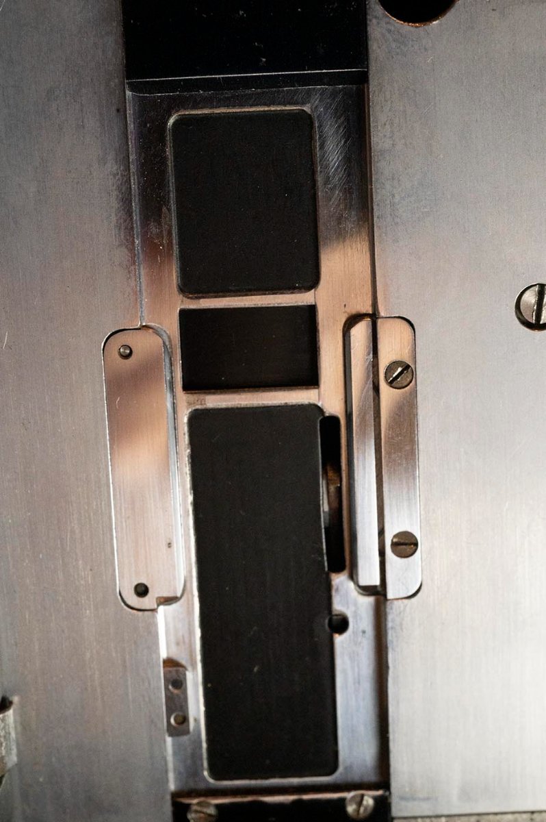
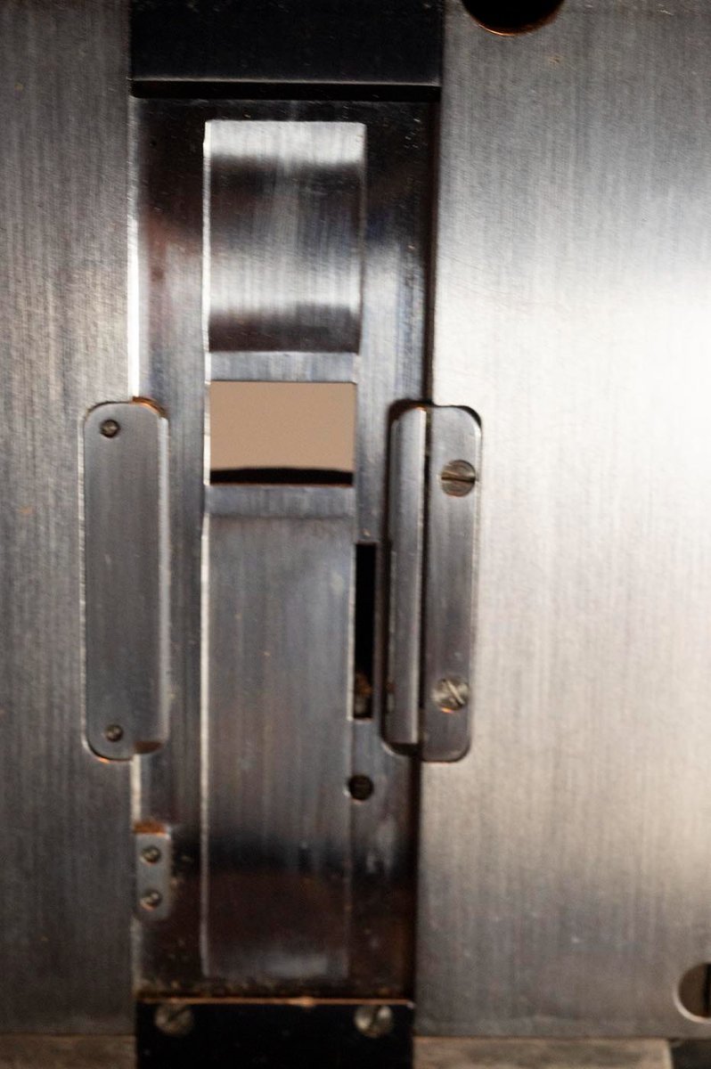
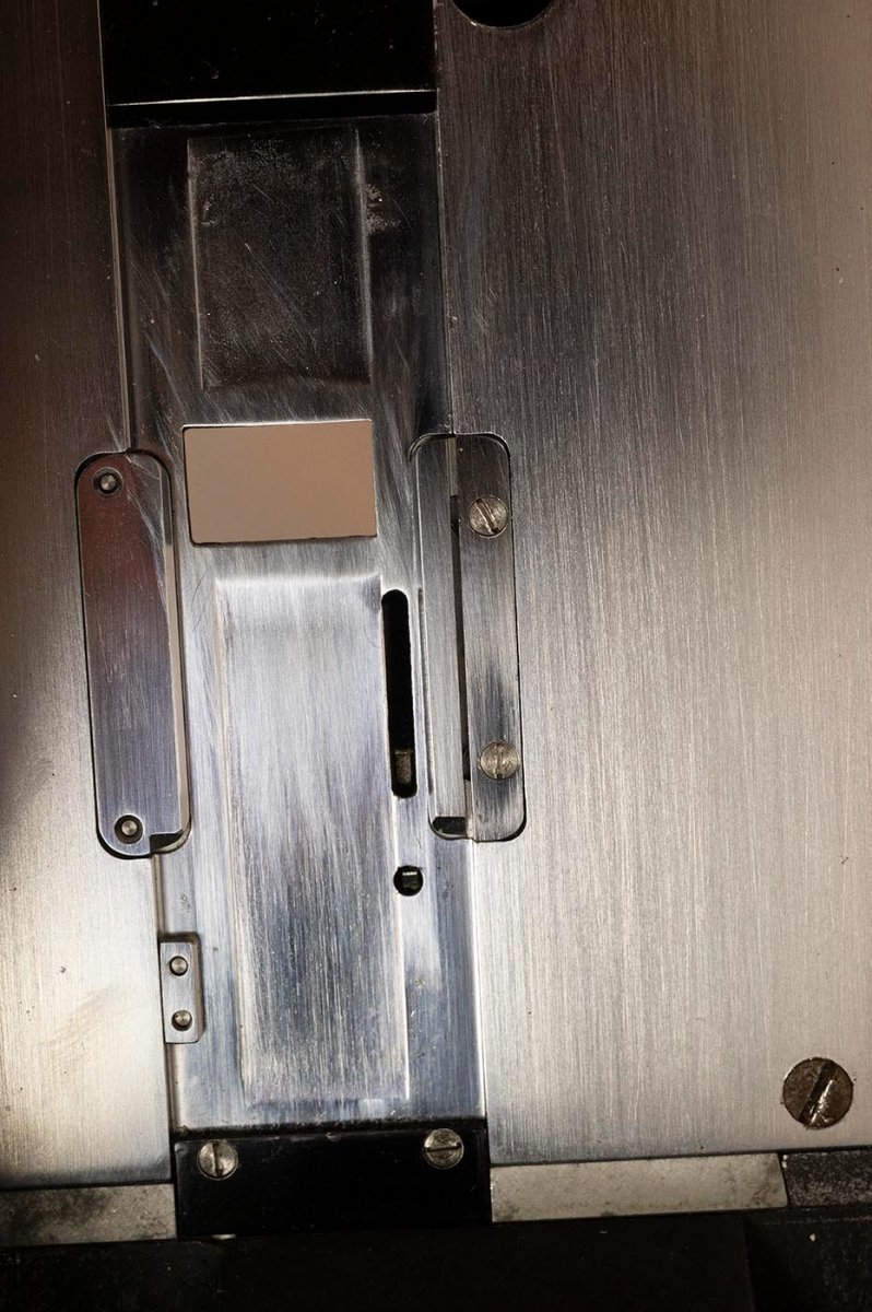
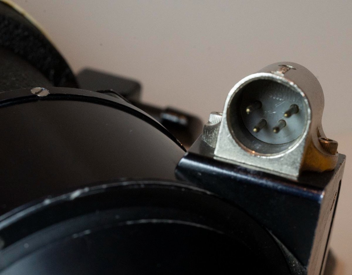
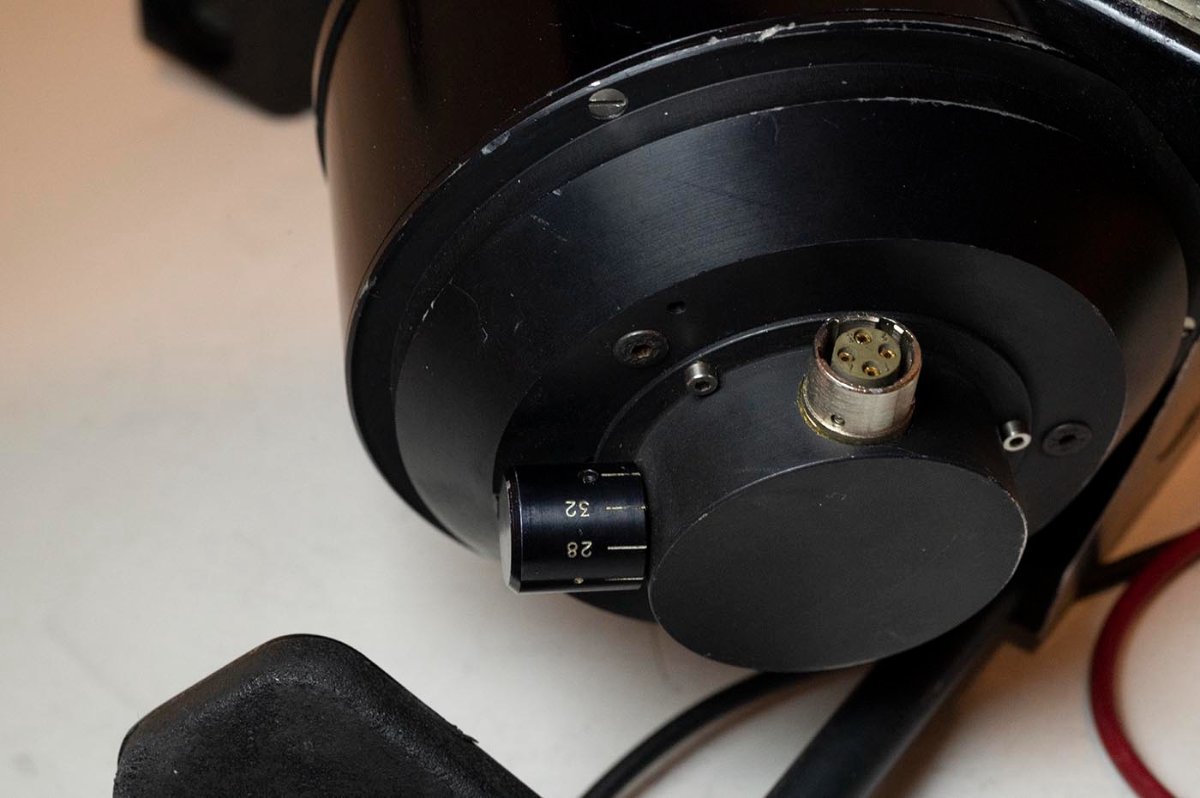
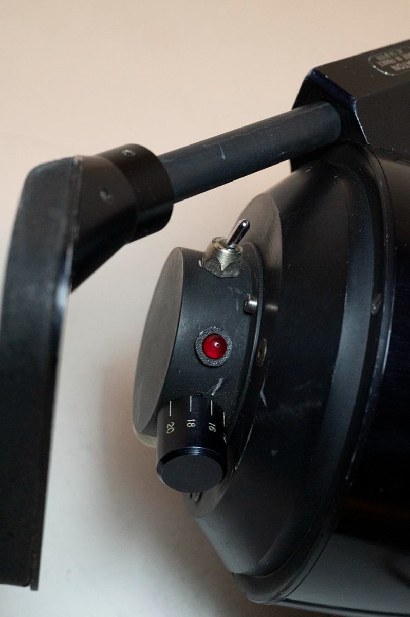
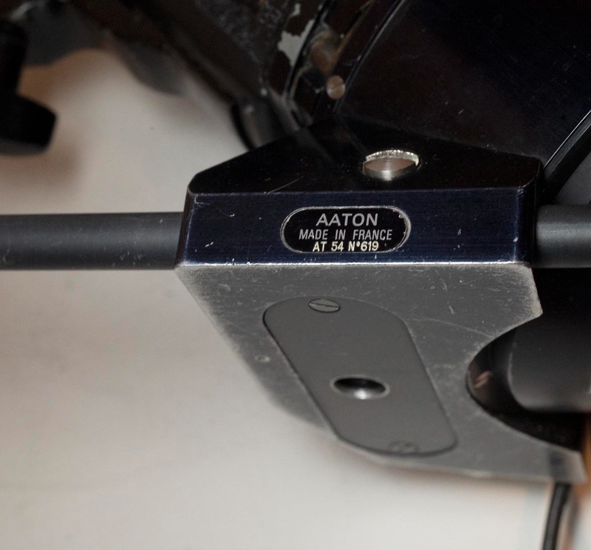
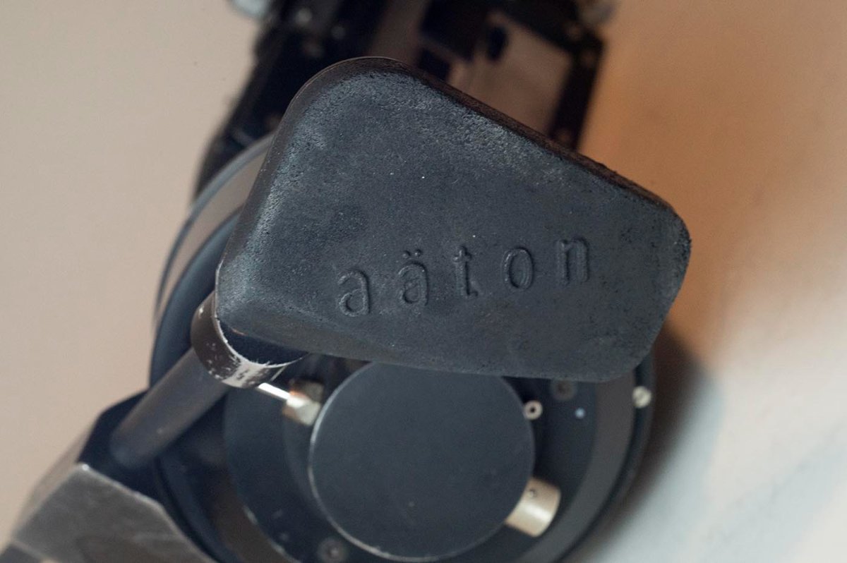
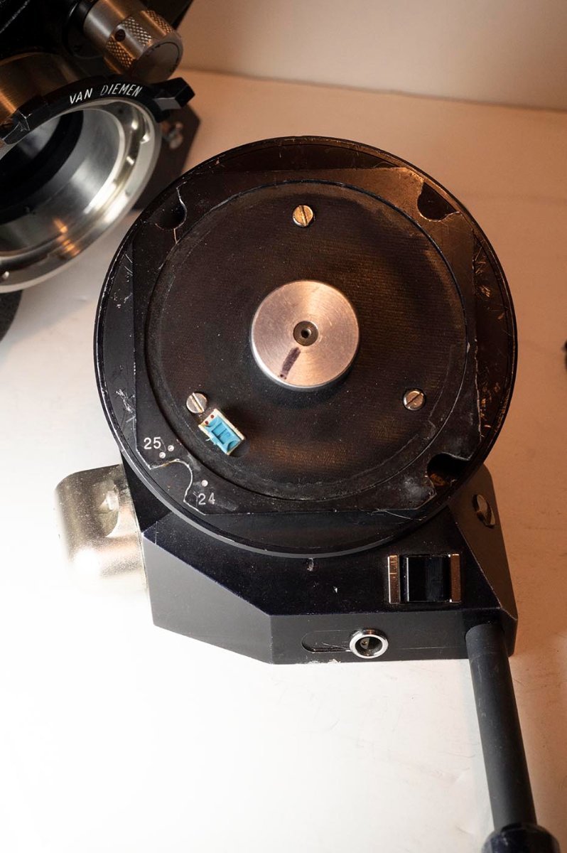
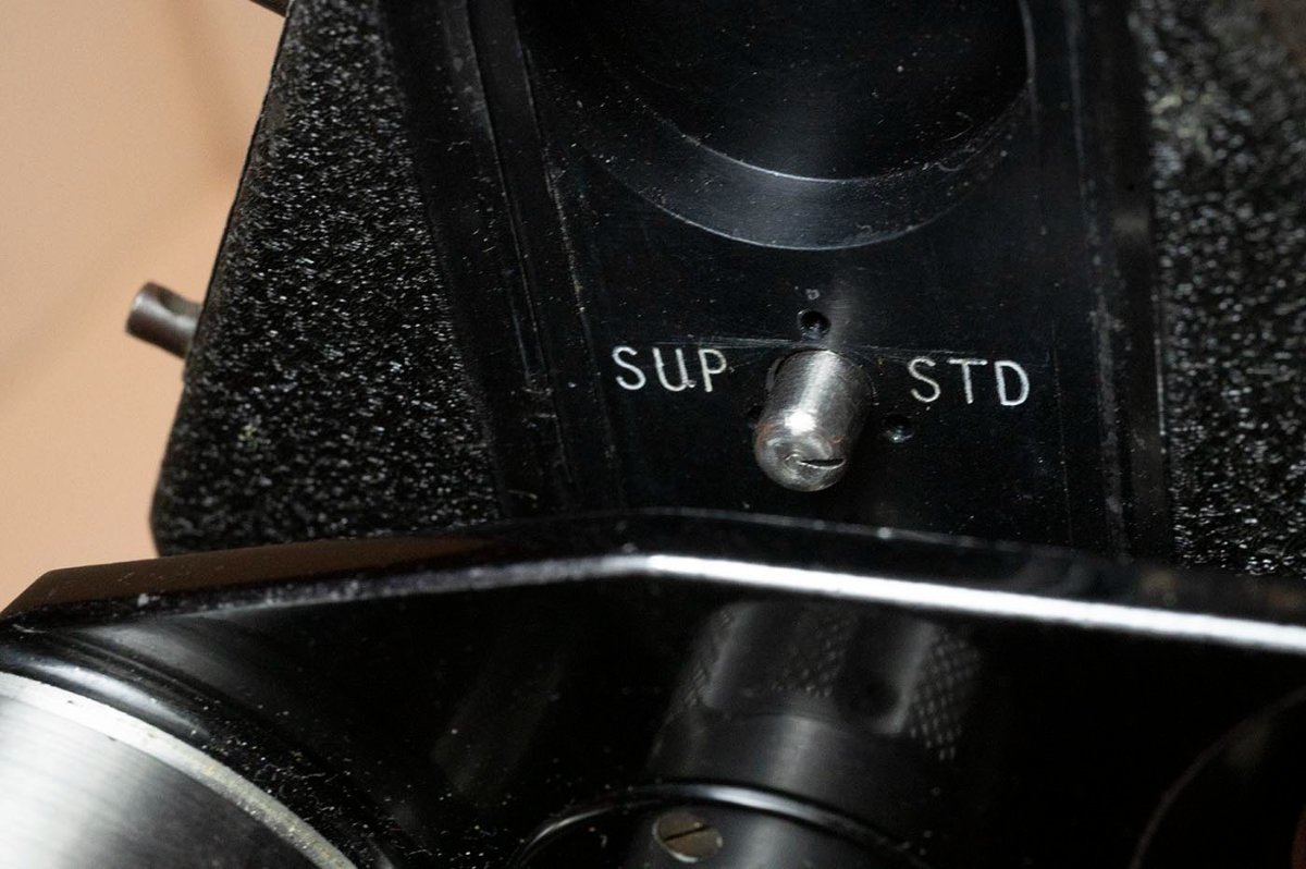
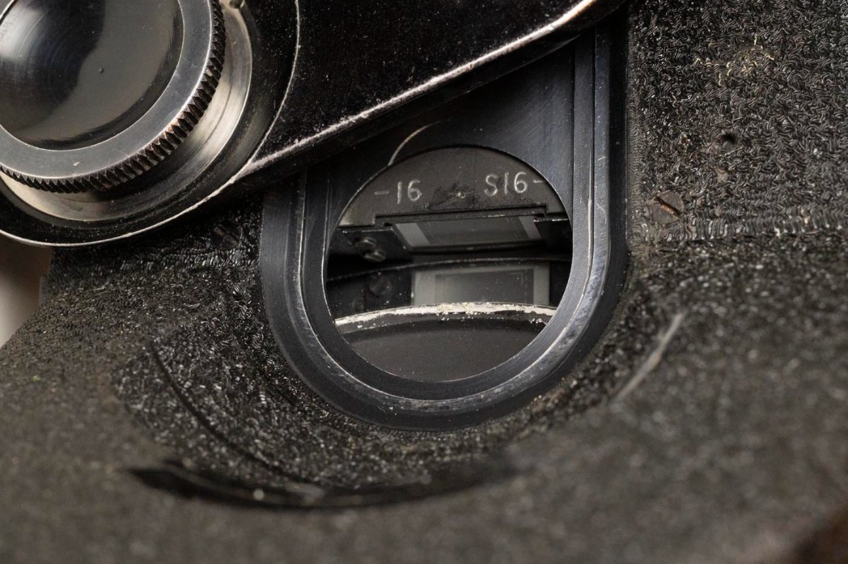
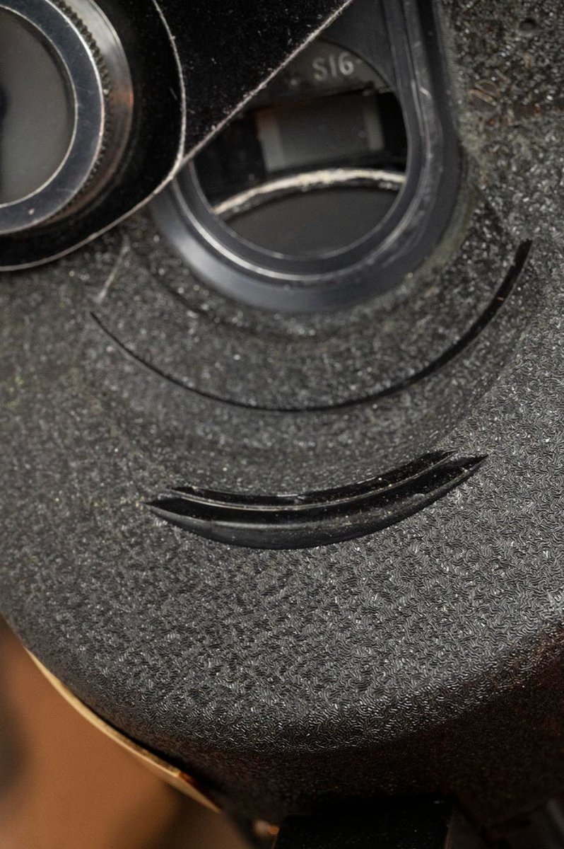
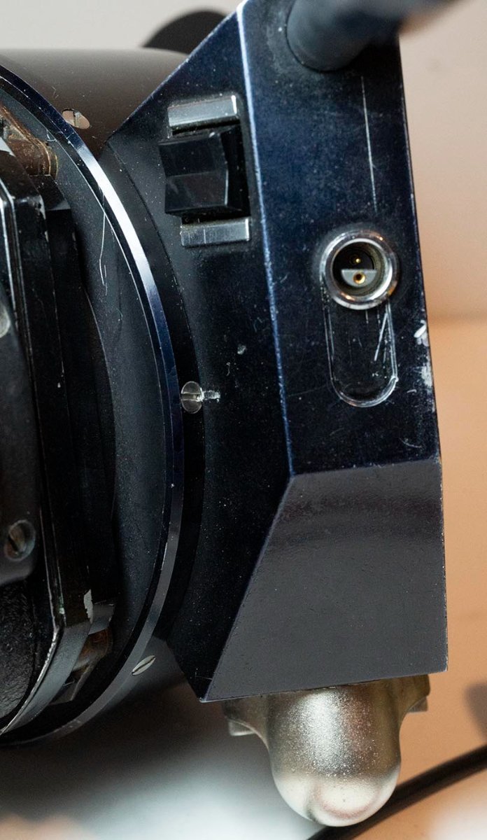
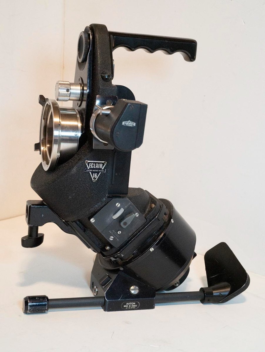
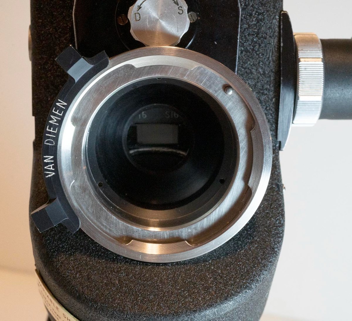
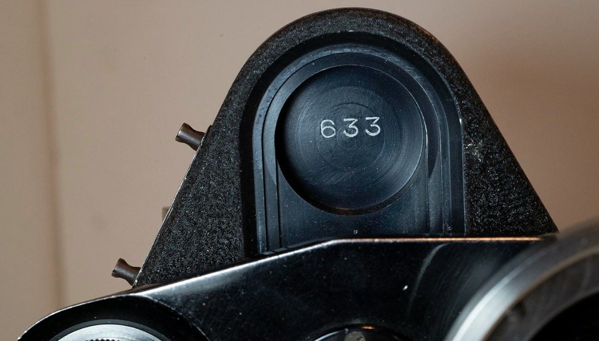
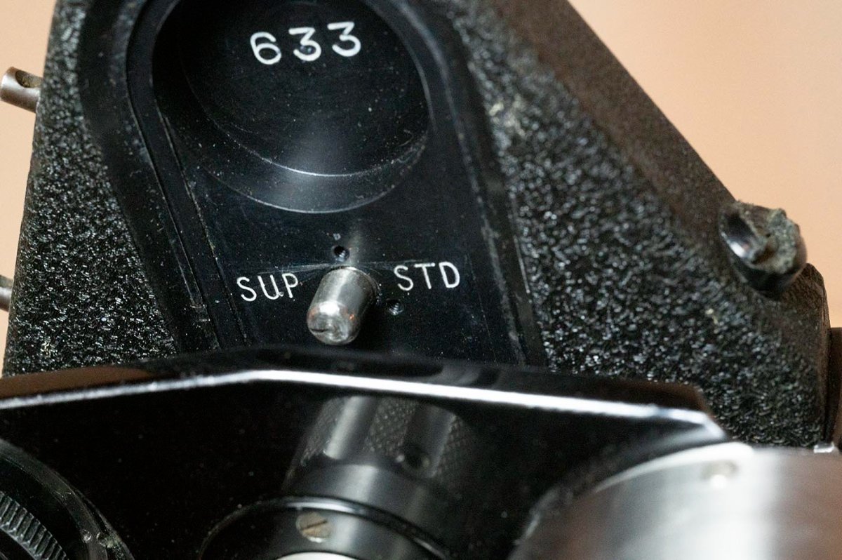
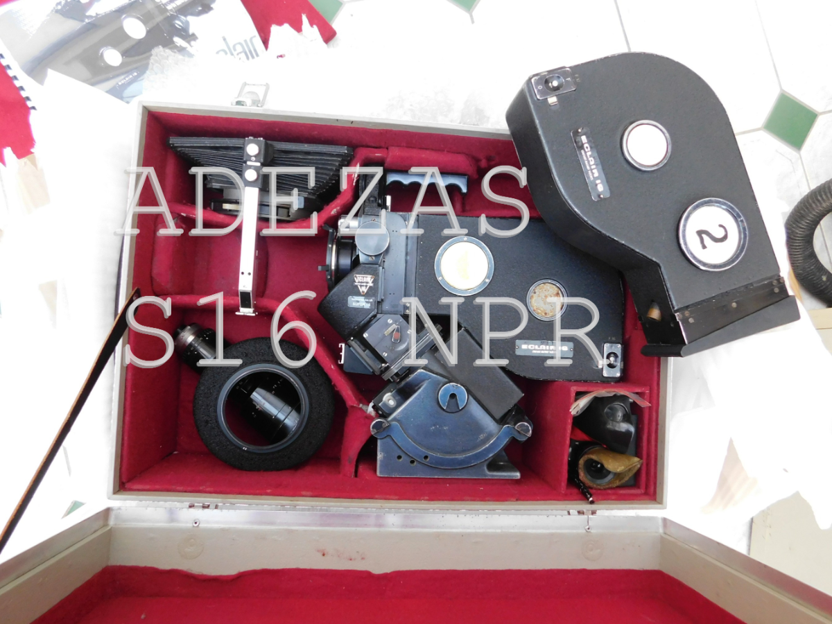
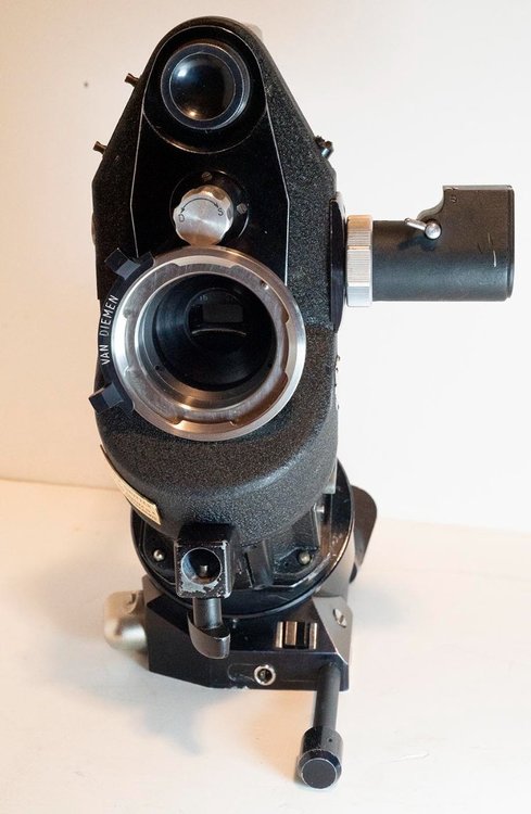
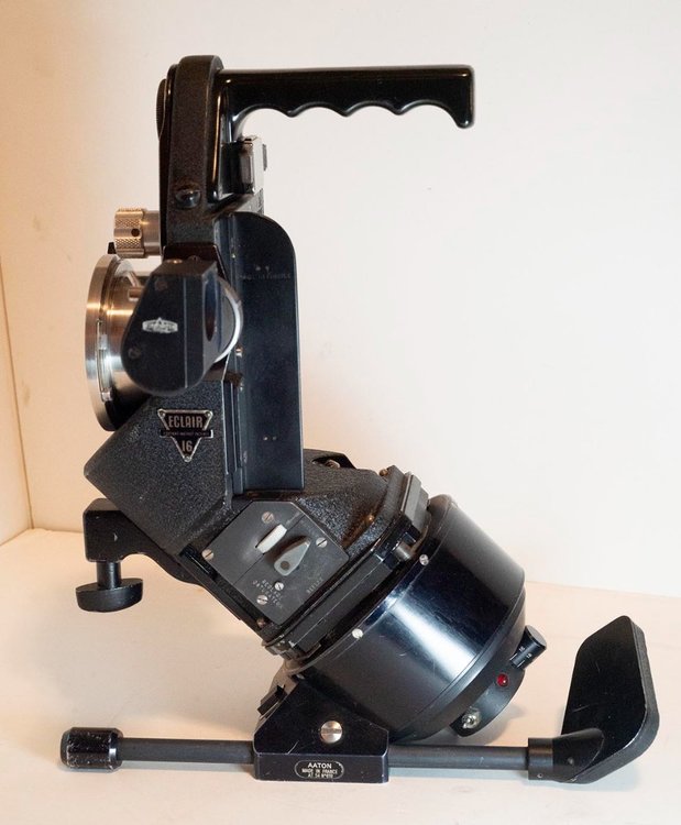
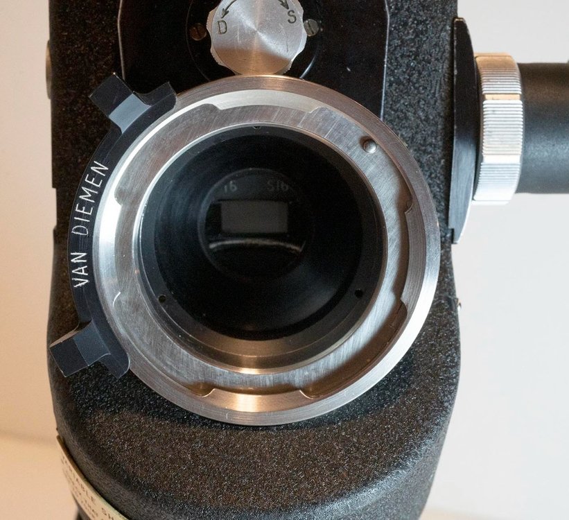
Just picked up this little gem - I wasn't sure it was what it is until I got it in my hands, but now I am. I think this is a factory S16 NPR, though it later had a PL mount put on it quite professionally, almost certainly by Van Diemen in the UK (since it's their mount, and I'm 99% sure they used to do stuff like that.) I'm saying it's factory, not converted later, because absolutely nobody is going to go to the trouble to engrave and paint-fill the markings like this has. If someone can verify that, say, Van Diemen actually did go to all that trouble, then I'll stand corrected. But for instance, their carving away of the body for the mount just got gloss black paint slapped on it, doesn't seem like their attention to detail went above and beyond to the level of engraved markings, you know? Some notes -- clearly it had a lot of double-perf film run through it in its life, as there is a wear spot around the bottom of the gate that matches up with the location and width of the other perf. -- When I pondered how you would recenter the mount on an NPR, I imagined the simplest thing to do would be to move the locating pin, since the mount already moves sides to side. When I pondered how you'd make it switchable back and forth I imagined an offset pin that could spin to two locations. Well lo and behold, Eclair imagined doing it the same way! -- If the engravings near the filter slot are supposed to let you know which format you're in, by noticing which one is clear and which one is slightly covered... well it's pretty damn subtle. Easier to spin the lens mount plate and look at the marker on the offset pin I'd say. -- I wondered how these motors could park in the mirror position, with a rubber coupling that allows the motor to be put on in any orientation. The answer is, the motor just lands in the same spot every time, it's up to you to put it in such that the spot it lands in every time is the spot where the mirror is in the right position. Simple but effective! There are guide marks but frankly just letting the motor come to rest under power, then assembling it on the camera without moving it, with the mirror centered, is all you need to do. -- The two positions of the motor switch are: to the left (from the operator's orientation) it clicks and stays on, in run position. To the right, it is a momentary switch that fires one frame, then when you take your finger off it springs back, then each time you press it one more frame. I assume the little two pin connecter next to it is for a remote switch for this function. -- The little toggle switch in the back, when pushed towards the rear of the camera, enables the speed dial. When pushed forward the motor always runs at 24/25fps (set with a separate switch on the hidden face of the motor), I assume as a quick way to get your sync speed without fiddling with the speed dial. -- Note that the gate plate is relieved all the way for the full S16 width. Compare this to the normal gate pictured, plus the gate from a parts camera I bought, that has been modified to (almost) be S16 width. Quite well done, actually, but still the extra image area is running on polished plate the whole way. Not sure if there's a significance to the black paint in the relieved areas vs the stock plate. OK, on with the pictures! Duncan


-
Eclair Flea Market
Duncan Brown replied to Gregg MacPherson's topic in Marketplace Listings Under $200 / €200
Bought it. Duncan -
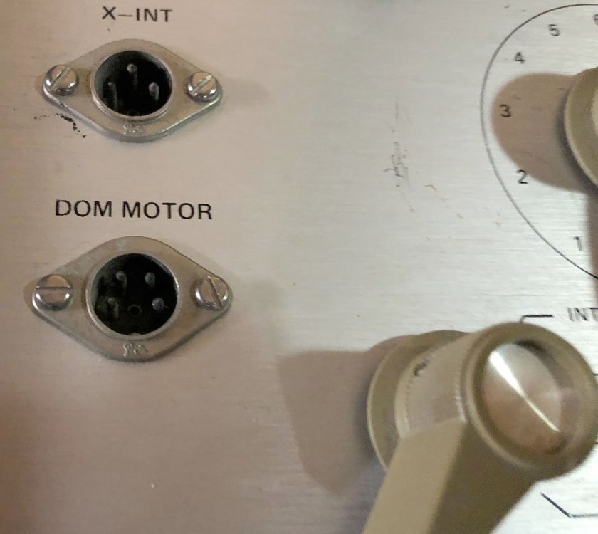
Haha yep that's pretty DUM ? Do you have the full instructions that presumably exist behind that last image you posted (the one with "Operating Instructions" at the top)? I have various pieces of that rig. An intervalometer manual would be cool too, if anyone has one. Though it's all pretty simplistic, just a matter of tracing out the wires inside if I have to. There's a dizzying array of connectors involved in all this stuff. Even things that look like they belong together are connectorized differently. The intervalometer has what look like male DIN connectors on the front panel, but with no provision for the shell that is usually around the outside of a cable-mounted female DIN connector. Looks like I will have to try de-outer-shelling some female DIN connectors and see if they fit. (Edited to add: I recently came up with one of those "Single frame gear" units too.) Duncan
-
I thought I'd seen this term more widely, but right now I can only find references in Arri stuff. DOM Motor seems to mean a motor that will single step, I think with one press stepping the motor to the point of opening the shutter, and then next press spinning it to the shutter closed position. I can't come up with any words that fit D-O-M. I just know it's going to be something stupid, like with "MOS Camera"... Duncan
-
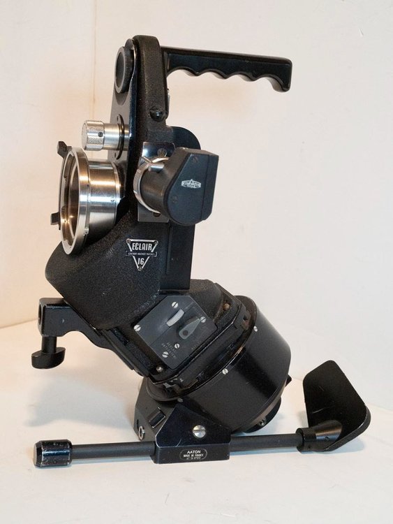
Couldn't find any previous discussion of this, so I thought I'd start a new topic. In this picture from a recent NPR for sale thread, I noticed the motor cradle does not look like my original NPR's cradle, but does look like the one with a stripped parts motor I got. It looks to me like it's designed to hook up with some sort of customized tripod head. But it must have been a production head, because that's two cradles I've seen like that now. Whats the story here? Duncan

-
Eclair Flea Market
Duncan Brown replied to Gregg MacPherson's topic in Marketplace Listings Under $200 / €200
You and me both ? Duncan -
OK, the new counter chips arrived. Put one in, and gloriously perfect precision square waves at all the right frequencies coming out of it. Put back in the old logic gate chip it was driving... everything all screwed up again. Pulled that chip out again and the counter outputs look perfect again. So it looks like BOTH of the chips I thought could be "the bad chip" are... "the bad chips". I'll have a new one of that second chip here next week and will try again. One chip dead after 50 years could be random. Two connected chips dead is more worrisome. Someone was in here static zapping things by touching them, or fed more than 5V in on the 5V line, or something, possibly. We'll see where this adventure leads next! Duncan
-
Why did all these companies come out with some of their coolest cameras and then hardly make any of them (I'm looking at you, official Arri Super16 16S). Well here's a big fancy brochure for Beaulieu's entry into that hall of infamy - the News16. Scanned at 600 dpi, it's a monster PDF (nearly 70MB) http://backglass.org/duncan/16mm/beaulieu_news16_brochure.pdf If you just want to read it and don't need that insane quality, I also usually make a 100DPI version of my scans. Here's this one at a kinder gentler 3MB: http://backglass.org/duncan/16mm/beaulieu_news16_brochure_100.pdf Enjoy! Duncan
-
Here's the speed ramping circuit in action on a scope: At rest it passes through the main 48KHz input signal to the output. (My scope is on the output.) When a 5V signal is applied to one of the connections to this board (as is done by the switch being in 50 or 75 positions in the assembled motor), the output signal frequency becomes a fraction of the input signal, quickly coming back to about half the frequency, where it pauses for a moment...before smoothly ramping back to the original frequency. I took a closer look at the board. There is a trace that takes the 48KHz signal from the basic crystal/counter circuitry and sends it to the dividers and logic that develop the signals for the stepper motor. This trace is cut on the original circuit board. The 48KHz signal instead gets sent over to this kludge board, along with 5V and ground. Then another wire sends it back again to where it was originally going as an input to the dividers and logic. So this is definitely a fix for problems that were found after the original design was "completed" but before this motor was sold. This logic is all automatic so that by giving it a lower input frequency, it sends a commensurately lower frequency to the stepper windings. This is a way to bring the stepper up to high speed a little more slowly, rather than the pulses to it instantly increasing in speed....something steppers don't generally like. Duncan
-
I got video of the speed ramping effect as seen by the scope, I'll try to post a link to that soon. I took out the chip that was being driven by the seemingly misbehaving chip. Still misbehaving. (A counter, not having the correct frequencies coming out of its various divided-frequency pins.) So I took out the misbehaving counter chip. I have some of those coming, probably get here next week. I'll put in the counter chip and see if its output then look correct. If so I'll put back in the chip it's driving and see if things still all look more correct. If so I might try temporarily reassembling the motor and seeing if it's working better. The ACL cycles through one complete frame in precisely one revolution of the motor. Now the question is, how many steps per revolution of this stepper motor? This stepper doesn't have strong enough magnets for me to "feel" the steps when spinning it slowly by hand. I'll obviously eventually figure out the answer by mapping out all the logic and doing the math, but it would be nice to know the answer from the motor side, as a sanity check. I'm not ready to try to pull that motor from the casing and look for a model number. SO many wires going to it through holes in the case. Duncan
-
WTB: Eclair ACL bits and pieces (motor, etc)
Duncan Brown replied to Duncan Brown's topic in Cine Marketplace
12 people have viewed my DVXUser WTB post in the first day or so and then it's been forgotten. Oh well, nice idea! Duncan -
Well the MIMUL motor speeds are all generated ultimately from a crystal oscillator, but the question is whether they all have a feedback system to maintain an utterly precise speed. I do note that the switch inputs for all the other speeds control one circuit, while the N position of the switch take a completely different path. (But that may just be because it needs to further determine whether it's 24 or 25fps). A hall effect sensor is simply a transistor that is controlled by a magnetic field instead of a base current. It is a way to "see" if a magnet is present or not. I'm guessing in this context it refers to the tachometer function of the motor - the stepper circuits drive the motor, while the hall effect circuits sense the resulting speed. Just like the motor is driven by magnetic effect, without the need for contact brushes, so too is the sensing done in a contactless manner. In scoping around the circuit yesterday I came across a chip not behaving correctly. Though it could also be the chip it is driving its signals into not behaving correctly. I think I will have to replace a chip or two before proceeding. That speed ramping circuit is COOL! Though that whole daughterboard has the looks of an "oopsie daisy" - a whole system designed and ready to go and then they find an issue that they have to develop a fix for and wedge in there somehow. The connections to the logic board are just tacked on to IC pins, they are not given their own connection points like they would be if it had been part of the original design. I'm imagining what happened is that they had the whole system finished, and it worked perfectly as they switched the knob from one position to the next, everything was great. Then the first actual user they handed it to spun the knob from 8 to 75 in an instant and the motor locked up, or ran backwards or something,. Oopise daisy! So what happens when that circuit is switched on is that the input frequency, which had just been passed through unchanged to the output pin, drops to a much much lower frequency (half or less) then slowly, across a second or two, ramps back up to match the input frequency.. That's more consistent with how stepper motors like to see their speed changed. I'll try to post a movie of that action on my oscilloscope later in the week when I get back to this project. Duncan
-
OK my camera seems to be from 1974, if yours is from 1976 and is NOT the later mirror-parking motor, perhaps they just made a mid-stream improvement by swapping the order of the wires on the switch and remarking the knob. Easy enough. If I ever get mine running correctly I'll see if my sub-8 position is actually inching. I don't think so but again maybe that was another improvement on the later one, to take advantage of the otherwise wasted extra position. Duncan
-
What is an inching speed? REallllllly slow? Is that different than just using the knob to do it by hand? So maybe that's what the sub-8 position is on this motor? And is that really the order of positions on the knob? Clearly the designer can attach the wires to the switch in whatever order they want, but in-numerical-order would seem to make more sense. Duncan
-
I've been working at this from a few directions at once, switching when I get frustrated or bored with one and moving on to another. The switch is made by EBE but uses an industry standard naming scheme. MX 2/4x6 MX is the size (17mm), 2 is the number of wafers (ganged switches stacked one on top of another), 4 is the number of poles (electrically separate switches, though they all move together) and 6 is the number of detent positions. The switches have 12 possible detent positions, so by mechanically limiting it to 6, you can have two switches operating together around 180 degrees each of the wafer. Then with two wafers, that's where you get the 4 switches. There is a "common wire" ring for each wafer that the switch connects to each contact in turn as you spin the switch. The common ring has two breaks in it, to make two 180 degree common rings for each wafer. That's a standard off the shelf part. In this case, they wanted to use the same common wire (+5V) for two of the sets of switches, so they bridged those gaps again with solder. The upper switch (nearest the knob) has one part that sends the 5V into 4 places in that convoluted logic, to select the speed 50/25/N/12 - apparently the default behavior of the circuit with no 5V signal being applied to any of the gates, is to select the 8 speed. Since the last two positions have no wire attached, this is where I get the notion that the position below 8 is just 8 again. The other upper switch sends the 5V one place for 50/25 and another place for all the others. One of the lower switches does the same thing. This is clearly involved in the fact that my motor went a fast speed at either 50/25 or a slow speed at all other positions. It's like there is a different way the circuitry controls the motor for the upper two speeds. The lower switches use two different common wires, and send their selected signals off to more motor-y things, not the logic things, so I haven't chased that all down yet. I will note that there are a LOT of wires going into that motor case, so that's going to be a whole other level of complexity to tackle at some point. There are 3 7493 4-bit binary counter chips. The first one simply takes the input frequency from the crystal and divides it down. I think the net result of that is a 48KHz signal feeding most of the rest of the logic. The other two work together to divide down the frequencies even more, with various divisions fed into this convoluted logic in different ways, but the main clock input to those comes from the little daughterboard attached to this logic board, so that frequency changes with the positions of the switch. That daughterboard is labeled "oscillateur à rampe variable" which google tells me means "variable ramp oscillator" so that all makes sense. Unfortunately, the two chips on that board have no markings on top, whether on purpose or not I can't tell. So that will be interesting to figure out schematically, but I can certainly investigate it with an oscilloscope (if I get it all running again!) One thing that makes it hard to do all this is the fact that everything is plastered with a "conformal coating" - clear goo that hardens and seals all the exposed metal pins and leads and traces away from the elements. Great for longevity, not so great for connecting meter or scope probes to parts. The secret is to do it from the back, where all pointy leads and pins are easily reached through the thin and easily broken coating. But it makes for a lot of flipping boards over and back, which is where wires start breaking. There are two components on the logic board that look like wirewound resistors and are in series with the logic signals, which makes no sense unless they are delay lines - an analog method of making signals have the desired timing relationship. That would be weird, but this whole design is a little weird. I cannot measure any conductivity through them. I sure hope that doesn't mean the voltage from my multimeter torched them? That would also be weird and make no sense that 5V would be fine but 9V would be fatal...but in order to do a delay line you need a ton of very tiny wire, so anything is possible I suppose. More investigation needed on those. Duncan

.jpg.681223f8db4446dcba1b217a7acc2567.jpg)