Aapo Lettinen
-
Posts
3,336 -
Joined
-
Last visited
Everything posted by Aapo Lettinen
-

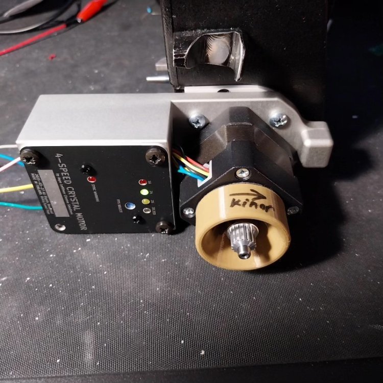
Anyone need a Crystal Sync motor for Kinor 16CX cameras?
Aapo Lettinen replied to Aapo Lettinen's topic in Russian Gear
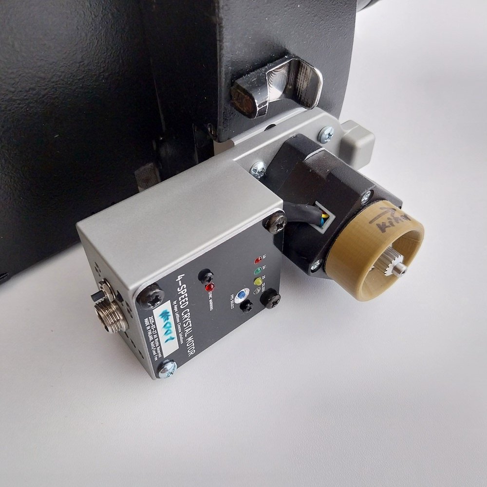
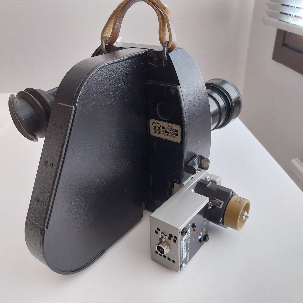
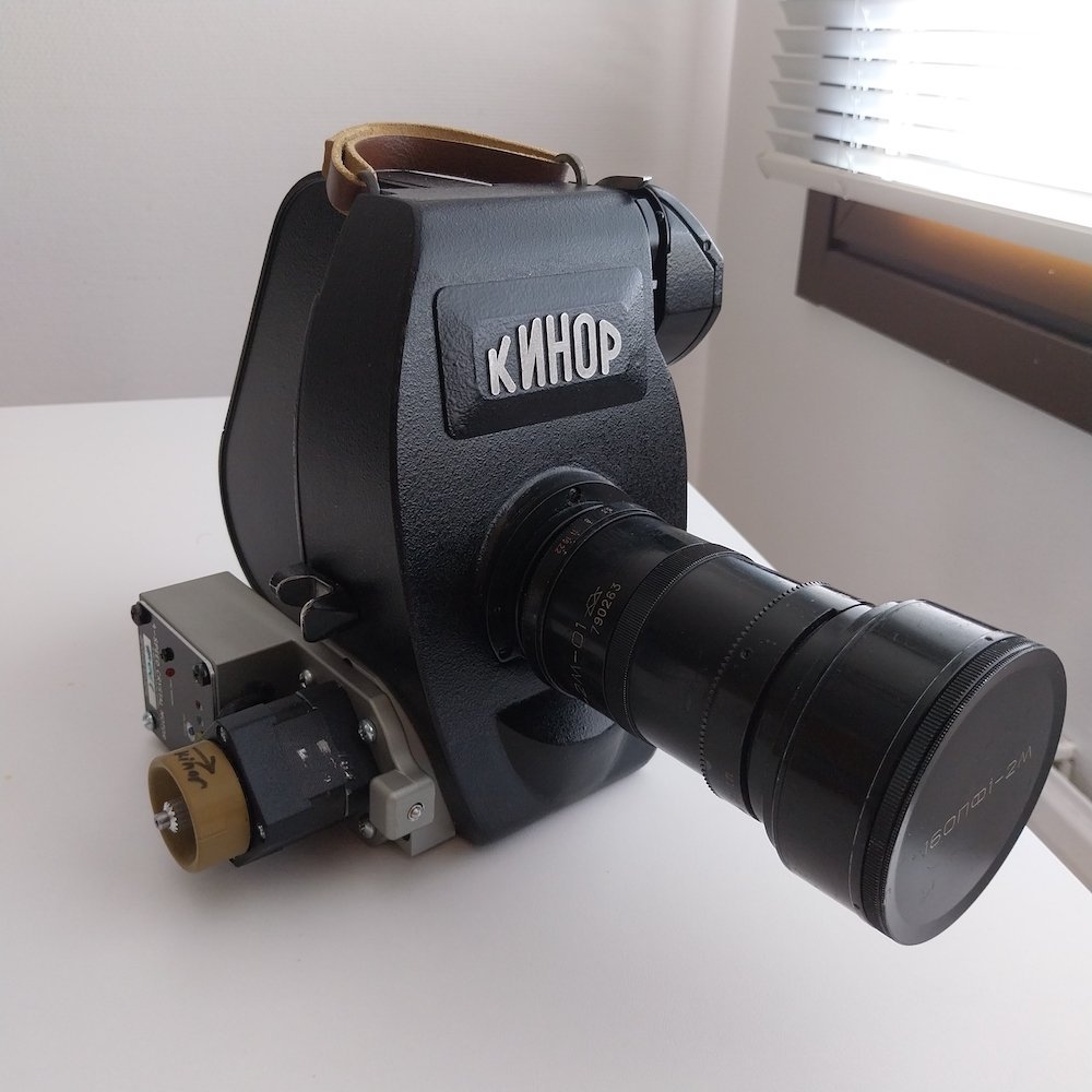
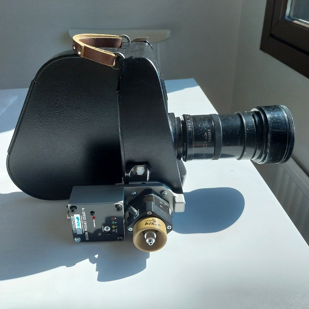
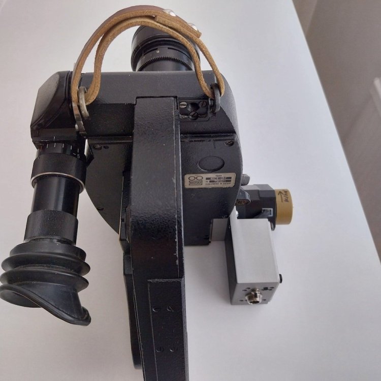
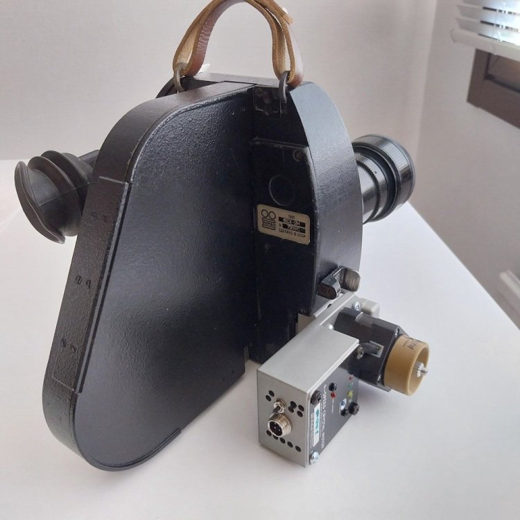
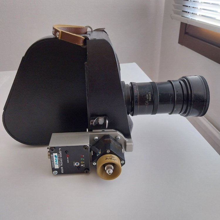
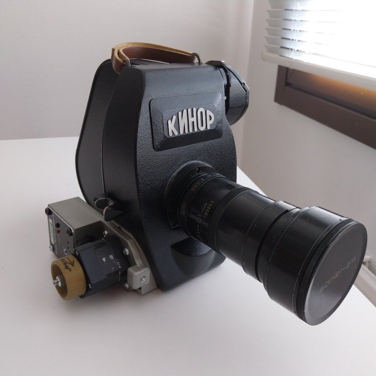
Starting to shoot tests and short film stuff with my Kinor and 4-speed crystal motor pretty soon. I will make a backet which allows installing a factory made off-the-shelf mini-Vlock battery plate like Smallrig or similar to the setup so that it is very compact and self-contained the great for run-and-gun type shooting. Notice how small the new motor is, this is about 4 times smaller than the original motor these cameras had! on the photos there is 100ft magazine and 12-120mm lens attached

-
photos of the Kinor16 with the new 4-speed motor for better size comparison. 100ft magazine and 12-120mm lens on the camera. I will design a bracket which allows installing a off-the-shelf Mini-Vlock plate like Smallrig or similar to the motor system, will need it for my own projects and will try to make it so that the bracket can be 3d printed if needed and not mandatory to be aluminium. When I'll have the mini-vlock system for power this setup will be great for run-and-gun type shooting.
-
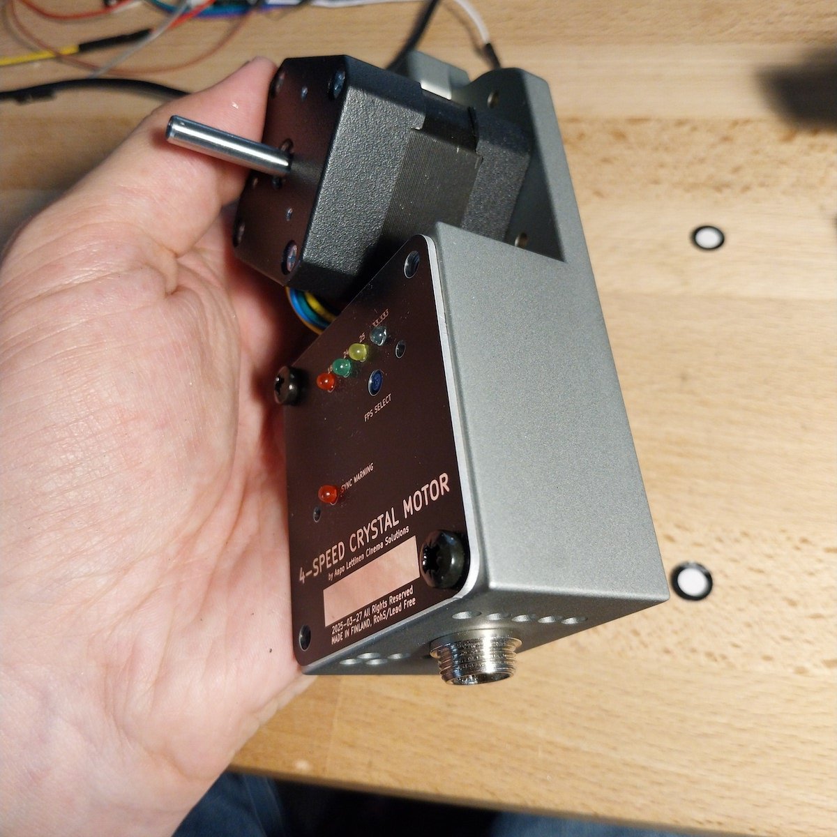
final software version and how the speed presets are arranged etc. the front panel is not final on the prototype, the final panel has larger hole for the button so that one can use it with finger easily
-
longer video with some talking about what I am doing
-
motor working with Kinor16, testing the crystal sync software version. this version was running about 0.015fps underspeed and corrected the difference in later versions. The final one is running very exact.
-
From the ebay pics it indeed looks like a extra crystal speed controller. Custom made with only couple of them made from the looks of it, just a project box with the panel and selector added. New external controllers for similar use can be made no problem, just need the info about how many pulses needed per frame (to calculate the needed signal frequency in Hz for each framerate) and the signal level needed (most old equipment has either 5v or 10v logic level)
-
1.4mm sounds like a casting/machining tolerance error considering that the main body is separate from the bottom of the camera where the thread is and they have likely manually drilled and tapped the thread. Surprising that it is not more off than a mm or so. it is likely that it will vary a tiny bit from camera to camera at least if different production batches but I guess would be within a mm from the target still. sounds like it is intended to be on dead center and if it is less than 2mm off it is a pretty good result I think considering that it is not possible to exactly accurately mount a screw either because they need to have some play to be useful and most screws are made with similar tooling than bolts meaning they are not exactly identical and the thread may be slightly off centre or have other variance
-
tried to measure but it is very difficult due to the camera not having any right angles to reference to close enough to the thread. On my camera it seems to be pretty close to the optical axis but can be couple of mm off. one method for measuring would be to have a line laser which is pointed so that it hits the center of the lens mount cap and the centerline of the attached 15mm rods at the same time and then seeing where it lands on the bottom of the camera. another method would be to 3d scan the front and bottom of the camera body with appropriate marks on the center of the lens mount and the center of the rods and if possible scan the backside too to get the centerline of the gate. then check from the 3d model how far off center the thread is from the common centerline of those. did you get the camera body already? I think you need to get some kind of 3d scanner and 3d printer in any case if wanting to design accessories for it. but if you only have the printer and not 3d scanner, you could print out a "measuring rig" which mounts to the rods and has a marker to precisely tune it to the center of the lens mount (or lens cap). Then the "measuring rig" extends to the bottom of the camera and has some kind of reference bar/surface you can use to measure the distance between the optical centerline and the actual tripod thread. OR you can just make the accessory first and then mount it and check if it is off and by how much. I sometimes do this if in a hurry and there is budget to make extra test pieces. Just guess the offset first, then make a test piece, mount it and measure how far it is off. if the possible offset is intentional it is likely some fixed amount of full millimeters so measure the approximate figure, guess to which direction the exact value is on the scale and then make another test piece with the guessed exact dimension. you may get it perfect on the second try or one extra version max. needed 🙂
-
new ALCS compact crystal motor for Eclair NPR
Aapo Lettinen replied to Aapo Lettinen's topic in Eclair
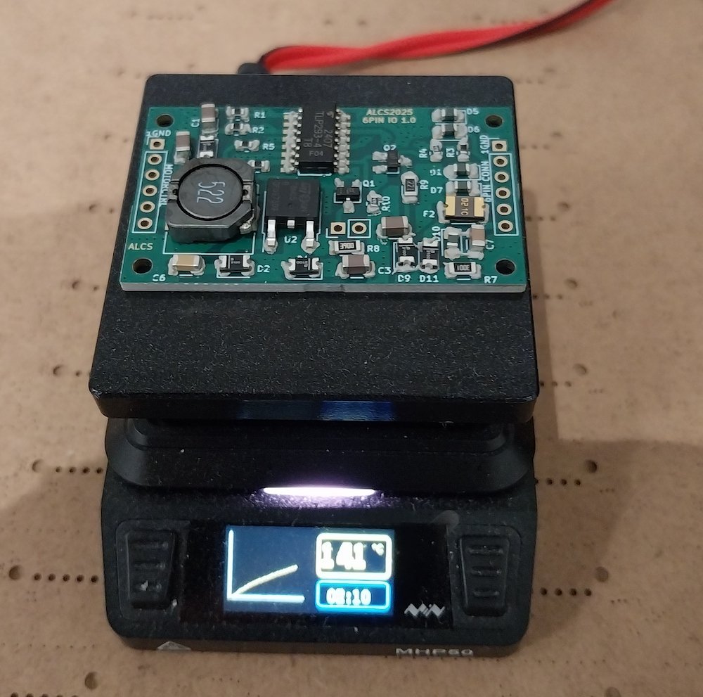
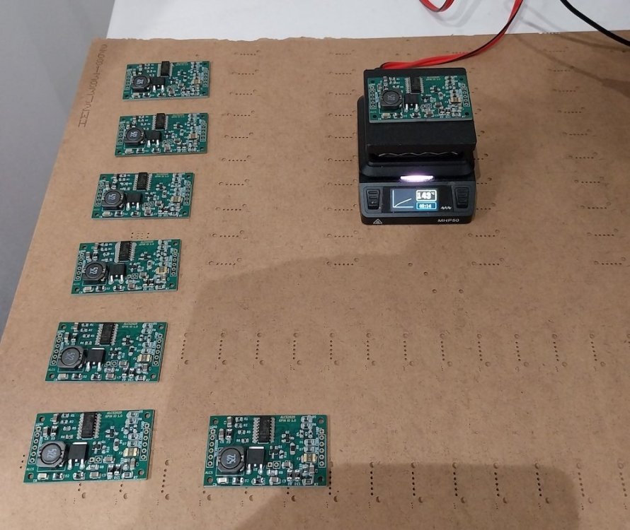
reflow soldering the 6-pin IO modules for my Eclair NPR and CP16R motor systems. this batch will mainly go to CP16R kits but there will be one or two spared for NPR motors 🙂 -
ALCS cp16r 45-speed crystal electronics
Aapo Lettinen replied to Aapo Lettinen's topic in Cinema Products
small video of the soldering process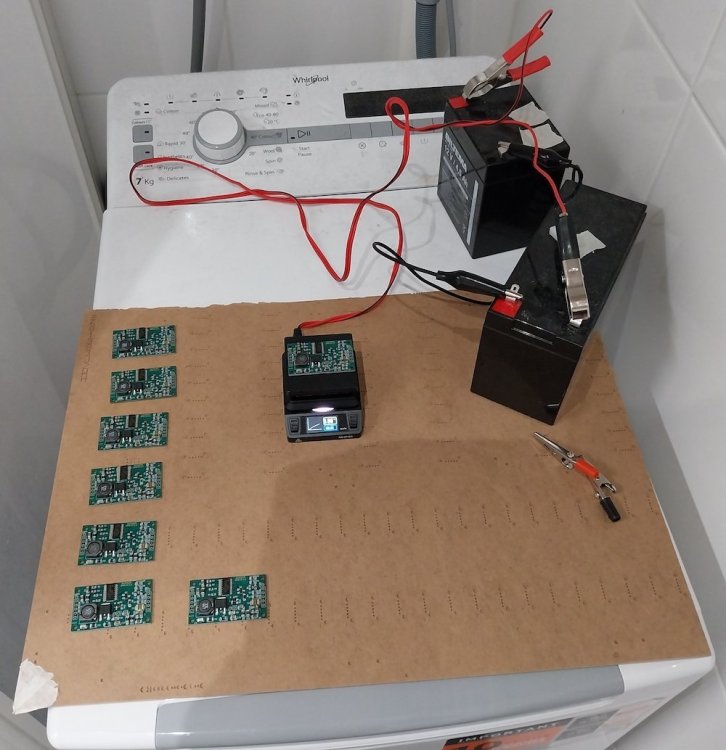

-
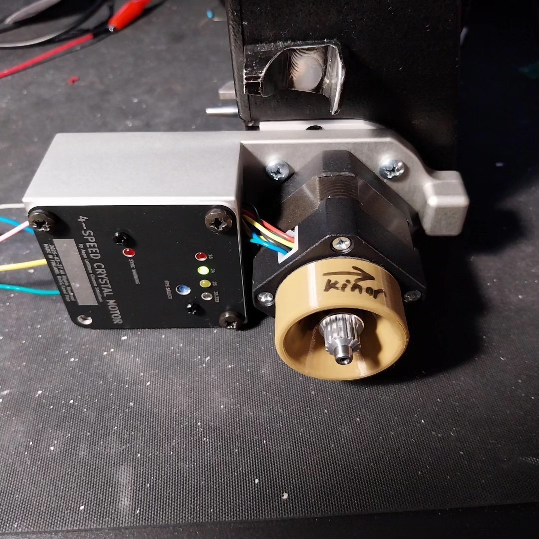
Testing the prototype unit with Kinor and fine tuning the software for best stability and response. Assembling the final motors later this week but will need to test the software with ACL camera too before can lock the final version and fully assemble all the motors in the batch
-
ALCS cp16r 45-speed crystal electronics
Aapo Lettinen replied to Aapo Lettinen's topic in Cinema Products
soldering the IO modules for the July batch of cp16r boards. Making 8 boards so there is the required 6 for the cp16r kits and two extra if there is soldering errors etc. and if those extra ones are fine too will use them later for other kits or Eclair NPR project.
-
new ALCS compact crystal motor for Eclair NPR
Aapo Lettinen replied to Aapo Lettinen's topic in Eclair
and of course I have a video too! https://www.youtube.com/watch?v=lxn50cdSLLU&list=PLXvIUtmF3OxsCOCdTi64M6i0LcuOxIrdj&index=3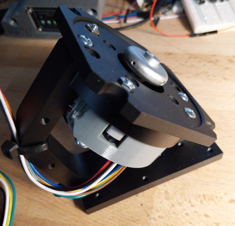
-
ALCS cp16r 45-speed crystal electronics
Aapo Lettinen replied to Aapo Lettinen's topic in Cinema Products
short circuit testing the IO module! if you are interested about some more detailed explanations and thermal imaging stuff then would be worth to watch https://www.youtube.com/watch?v=h1HIezIFwLY&list=PLXvIUtmF3OxtXFJWzSw8QLiw7tE6wisO_&index=1 -
new ALCS compact crystal motor for Eclair NPR
Aapo Lettinen replied to Aapo Lettinen's topic in Eclair
finessing the vibration reduction mount design now. all the other inner mechanics are ready and the prototype is using the final electric motor type now. just fine tuning the design of that grey rubber-like polyurethane ring which reduces motor noise to get the shape optimal. This assembly can already turn the camera and now when I have the outer shape and dimensions of that grey shockmount ring it is possible to continue designing the outer covers of the motor and the final circuit boards which go underneath the shockmount assembly.
-
the new magazine uses normal Kodak aluminium daylight spools for both feed and takeup so there is no need to rewind film. just load a factory 100ft roll and takeup is on similar 100ft daylight spool. people were worried about the availability of original 200ft A-minima spools so I will skip that original plastic spool system entirely and make the magazine use the boring common 100ft aluminium spools everyone else uses including the Bolex and K3 people 🙂 ---------------------- if needing the 400ft magazine version there is very limited time window for ordering, need to know in July2025 if it is needed and partially paid for in early August so that I can start making it at the same time than the 100ft version. If missing this time window the possibility to make 400ft is lost or even in the very best case someone would need to send their own camera to me for 3 or 4 months for additional testing and design work if losing this possibility to develop the two mag versions side by side
-
a short video about the aluminium casings and other stuff https://www.youtube.com/watch?v=Gl5IMaj5WIY
-
ALCS cp16r 45-speed crystal electronics
Aapo Lettinen replied to Aapo Lettinen's topic in Cinema Products
longer video with explanation https://www.youtube.com/watch?v=awlTwf3nyZA -
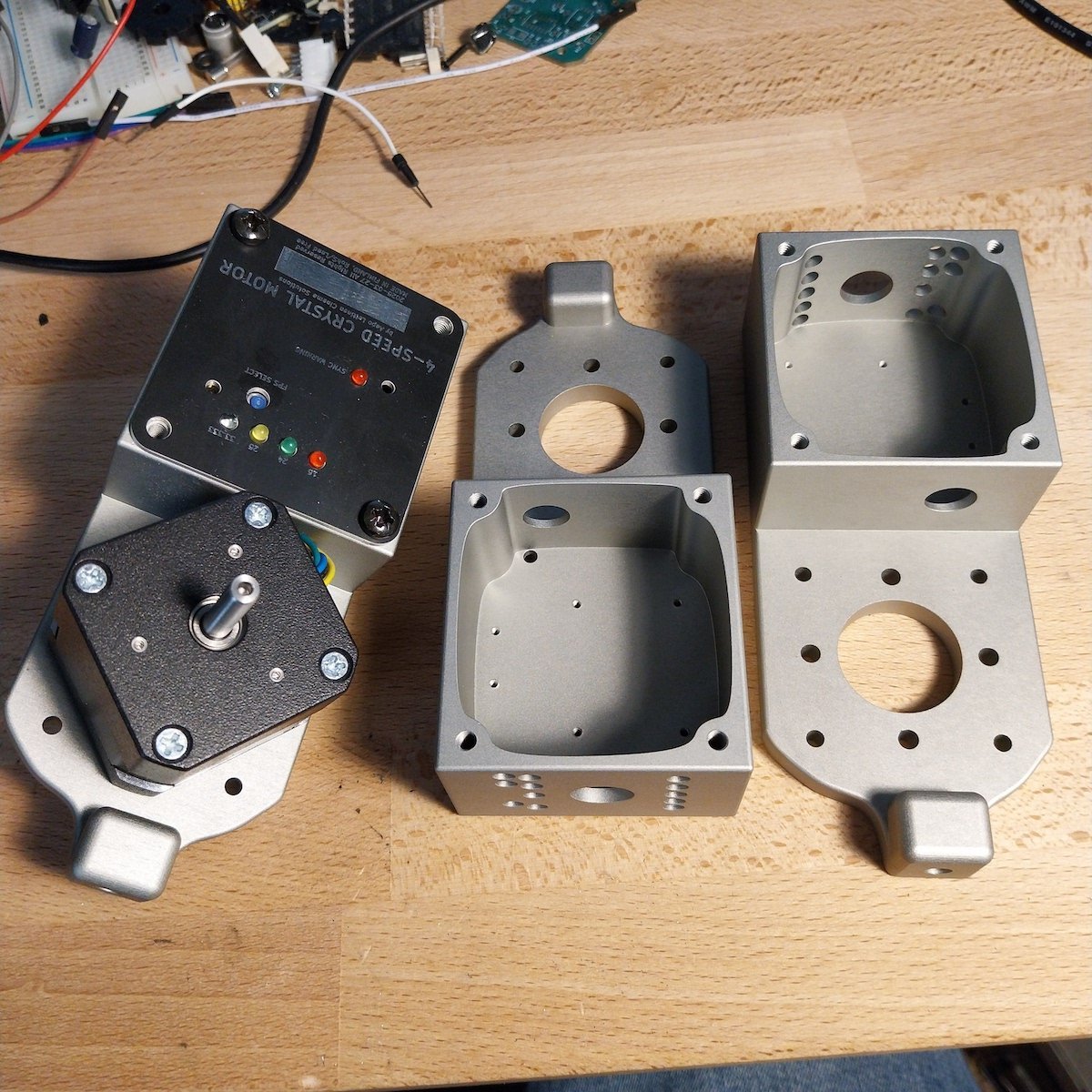
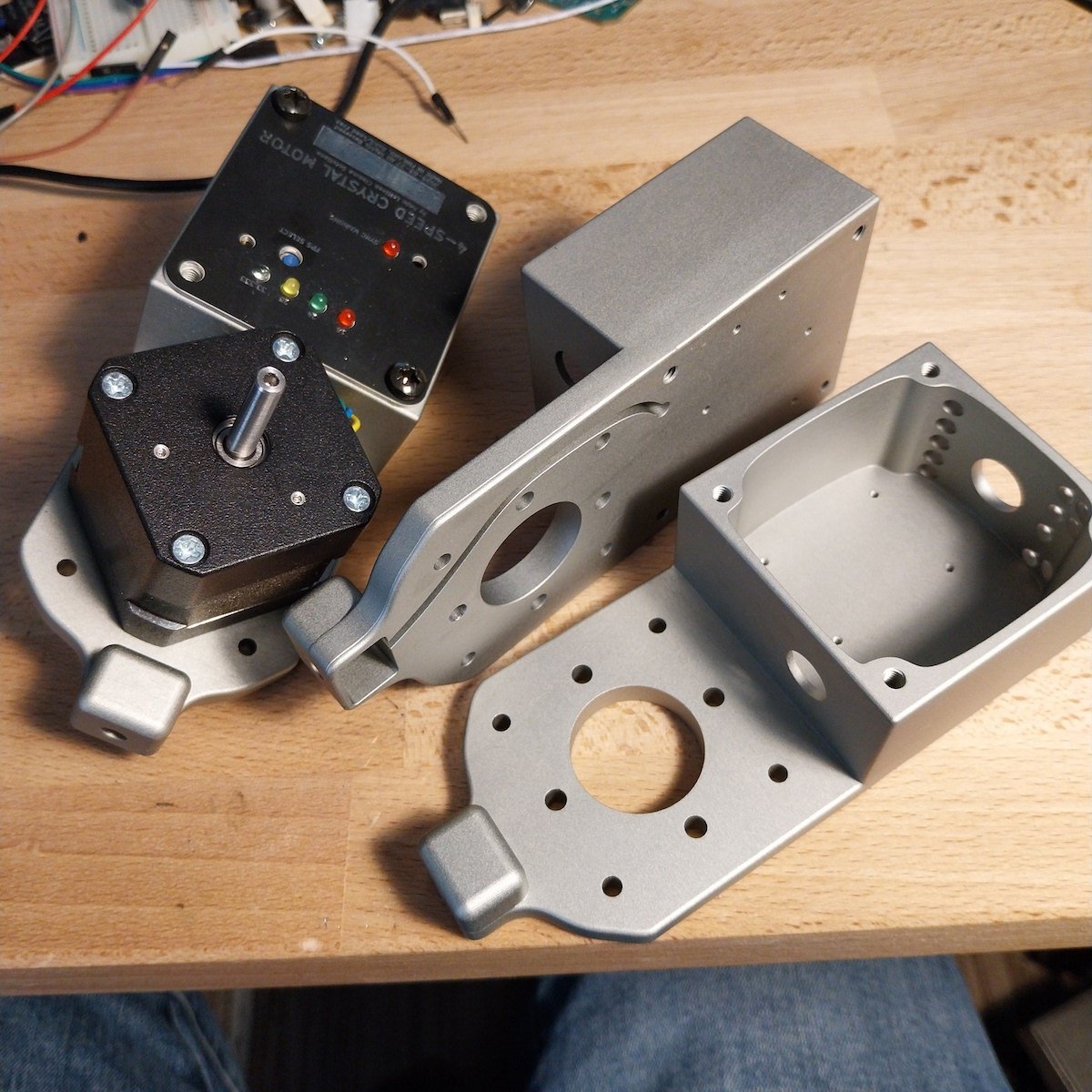
Final 4-speed motor aluminium bodies arrived today! Will assemble these first 3 next week. There is one test motor for me and the other two are already sold, but if needing a motor like this I will make more in August2025 and you can order from that batch 🙂


-
My A-Minima magazine project is moving forward now. Working on a newly made magazine which allows using standard aluminium 100ft daylight spools with the camera. Should have some kind of prototype in September and the final mags shipping before Christmas. I may post some 3d printed examples in August already when tuning the design. Price depends on how many ordered and when they are paid for. Preordered ones are considerably cheaper and preorders will help improving the finishing quality so highly recommended to contact me early on if interested in ordering these magazines. Approx target price for preordered ones is 2.5k or something like that. I will probably make one batch of preordered ones and maybe later on next year one extra batch which is more expensive, about 30% more expensive probably. Will try to keep the price under 3k in any case. They will be cnc machined in any case, made mostly out of aluminium and aiming for very good price-quality ratio. I should have possibility to make 400ft core load mags too if preordered very early on but they would be much more expensive than the 100ft. I would estimate from 4k to 5k price for the 400ft as it needs advanced electronics and more cnc parts and film testing. Dm here or on instagram (aaplet14). Facebook messages don't work
-
ALCS cp16r 45-speed crystal electronics
Aapo Lettinen replied to Aapo Lettinen's topic in Cinema Products
Testing the frequency response of the 6-pin IO module which is shared with the NPR and CP16R projects. doing couple of more tests and then starting to assemble the IO-modules for the final motors https://www.youtube.com/shorts/MSnojN3ciAY -
new ALCS compact crystal motor for Eclair NPR
Aapo Lettinen replied to Aapo Lettinen's topic in Eclair
Testing the frequency response of the 6-pin IO module which is shared with the NPR and CP16R projects. doing couple of more tests and then starting to assemble the IO-modules for the final motors https://www.youtube.com/shorts/MSnojN3ciAY -
ALCS cp16r 45-speed crystal electronics
Aapo Lettinen replied to Aapo Lettinen's topic in Cinema Products
Had to make a small change to the main board to enhance shutter sensor mechanical fitting and move a mounting hole a tiny bit. Waiting for new boards to arrive and working on the software in the meantime. Estimated shipping date is between 12th and 15th July for the preordered kits. I will make couple of extra ones half assembled and can finish them in late August/early September. If wanting to order those next batch ones one can get them for 850usd a piece including shipping if ordered now. Later on they cost from 900 to 950 with shipping. Looks like availability will be limited all the time so necessary to preorder if wanting a installation kit from future batches -
Anyone need a Crystal Sync motor for Kinor 16CX cameras?
Aapo Lettinen replied to Aapo Lettinen's topic in Russian Gear
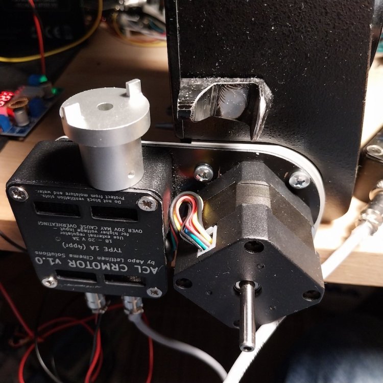
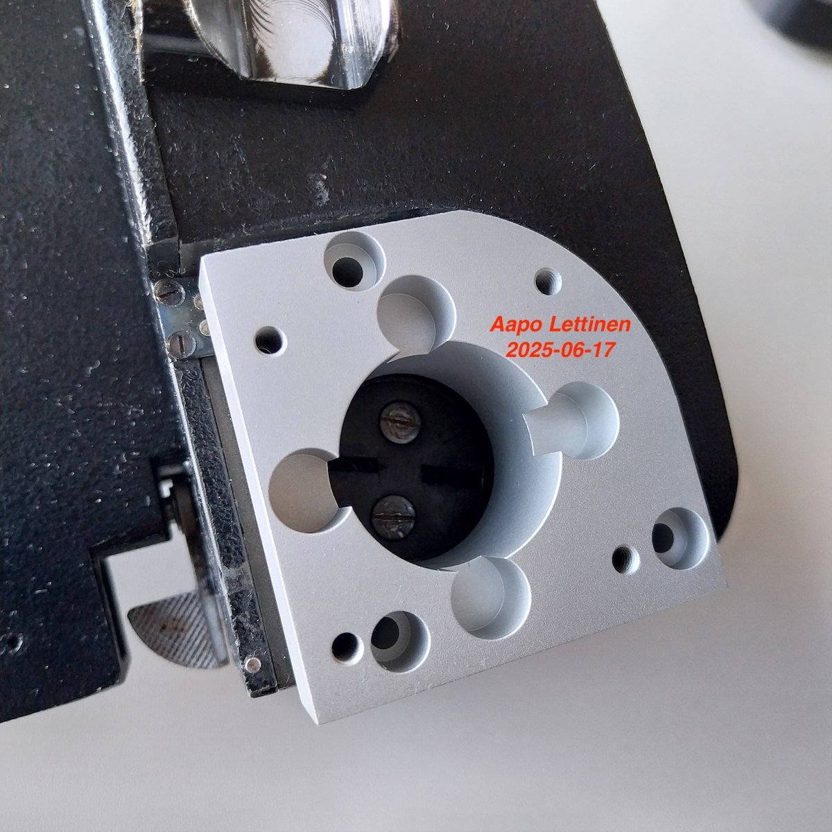
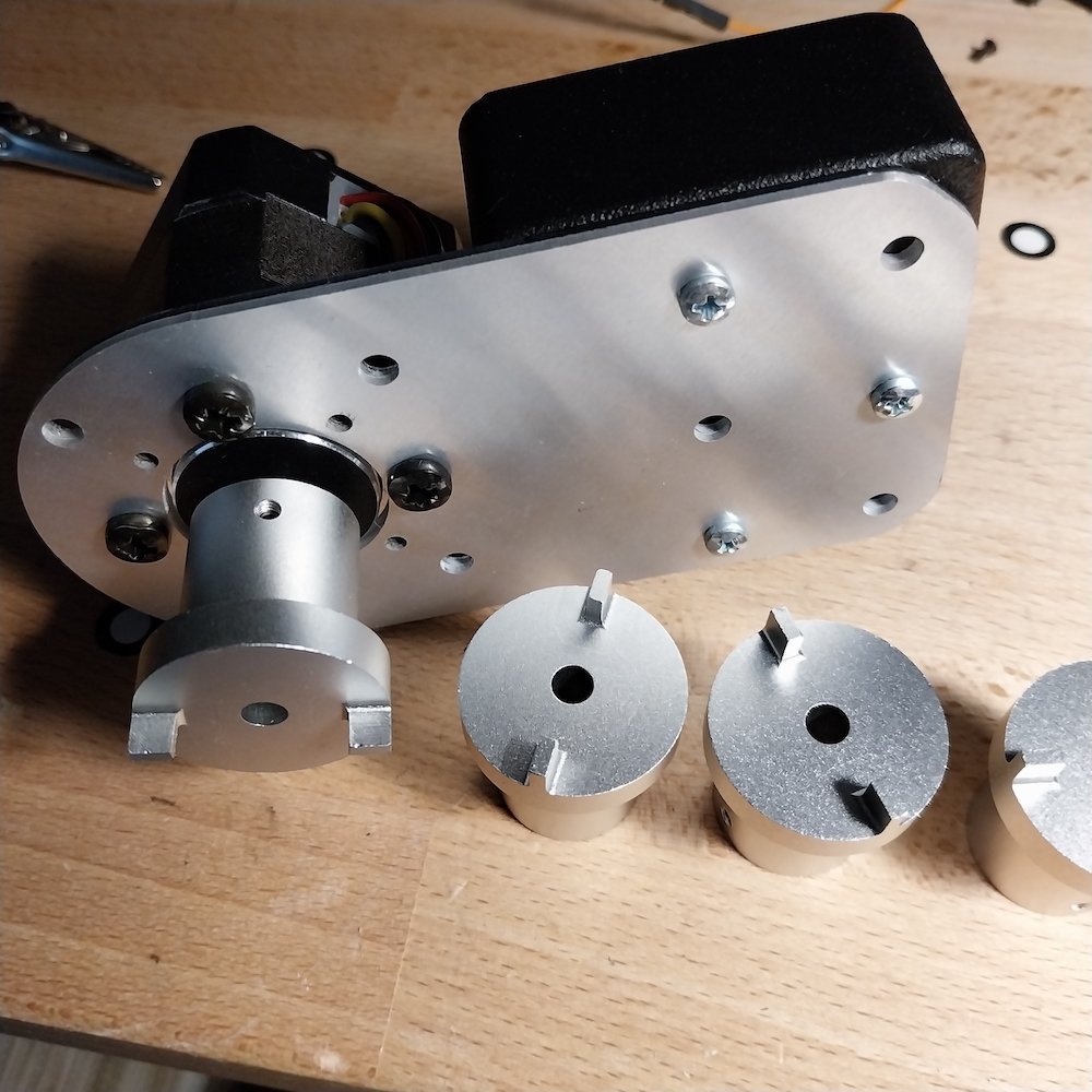
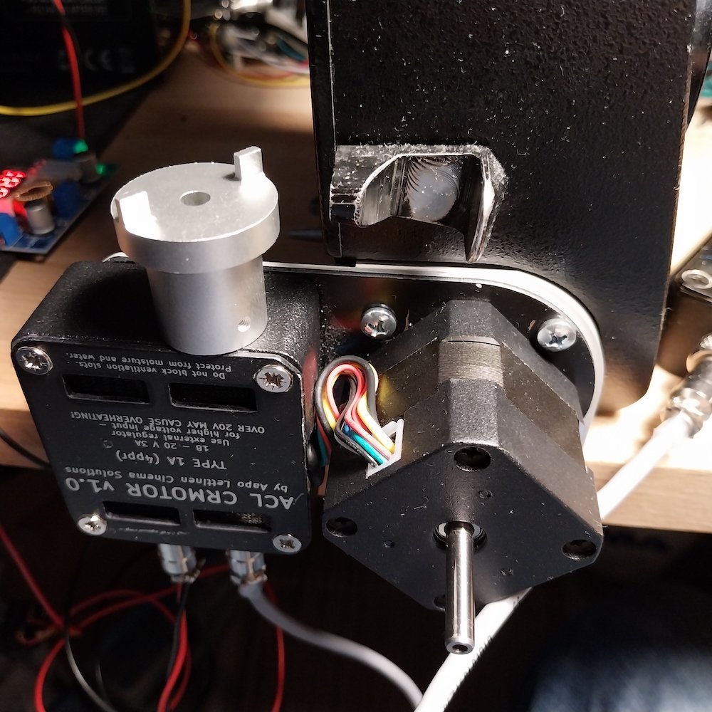
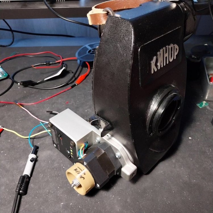
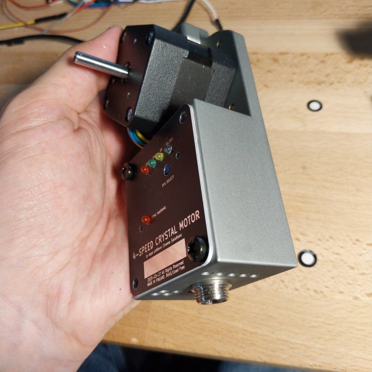
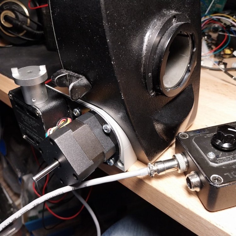
finished the mounting plate and axle adapter to mount my Universal motors to Kinor. tested here with my old 12-speed ACL motor as it has the same mounting system and was easiest available. Will use 10-speed and 4-speed Universal motors with the Kinor https://www.youtube.com/watch?v=66tdXrgfXXc&list=PLXvIUtmF3OxswaCvqLMXPKLQsvMZx9zpo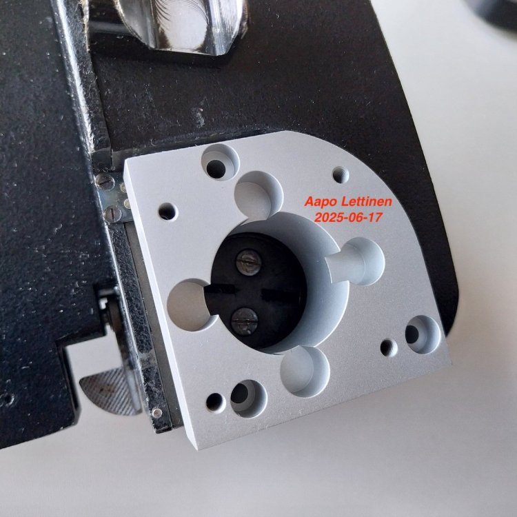

-
Finished Kinor16 axle adapter and mounting plate, testing with my 12-speed Eclair ACL motor. I will make 10-speed and 4-speed Universal motors for my own camera, it was just quickest to check with my old 12-speed system because it has same mounting and was immediately available 🙂 So all the mechanical parts are finished now. Will wait for the 4-speed motor bodies to arrive and will then start assembling. Works fine with the Kinor https://www.youtube.com/watch?v=66tdXrgfXXc&list=PLXvIUtmF3OxswaCvqLMXPKLQsvMZx9zpo