Gregg MacPherson
-
Posts
2,638 -
Joined
-
Last visited
Everything posted by Gregg MacPherson
-
English ACL 400' mags. Facts and Myths...
Gregg MacPherson replied to Gregg MacPherson's topic in Eclair
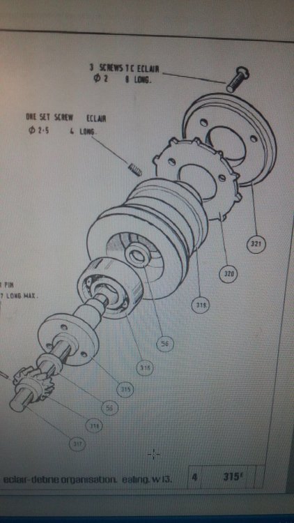
Mags falling off the camera..fact vs myth. The pertains to French mags as well, I believe, unless they have a difference in the geometry of the retaining mechanism that I didn't notice. If the mag retaining mechanism has too little spring force then the mag can fall off if the camera gets a big vertical jolt. Happened to me once jumping off a truck, holding just the top handle (zoom mounted, battery on belt). Mag landed ass first on very compacted, fine gravely road and was fine. Some writer(s) on the web describe this as if it's a generic design flaw. The retaining mechanism was I'm sure not changed with the intro of 400' mags, so perhaps the designers are at fault. Does anyone know if there were any changes to the latch or springs in the history of ACL? (excluding the obvious latch cover) Adjusting the spring force I found quite easy, by shimming under the catch tooth plate on the mag, #310 in Eng drawing below. Can't remember how thick the shiming, maybe 3 or more layers of tinfoil from a coffee can or something. If I added too much I think the latch wouldn't quite open, so that puts a constraint on it. If all mag fronts have the same dimensions (I wondered) then you have to shim all the same. A better method might be to modify or replace the release lever spring. See the UK parts catalogue for a drawing. So, fact or myth? Gregg.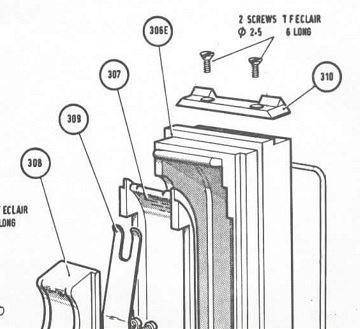
-
Heikki, I'm glad (relieved) that you enjoy the humor... Perhaps a correction on my hastily introduced reference axes above. Most common convention for drawing may be the right hand rule (RHR). Thumb vertical, index finger pointing, second finger at 90 deg, so Z, X, Y, all positive. Sometimes the LHR is used in some engineering fields. Doesn't matter much, but if we use these spatial references, lets use the RHR. Gregg.
-
Eclair ACL 1.5 newbie questions (with pictures!)
Gregg MacPherson replied to Duncan Brown's topic in Eclair
Sooner or later you'll get the motor schematics. That website opened for me and was interesting. Google translate worked well. Didn't yet see anything about ACL. Did see pics of electronics for Aaton motor and camera base. Lots of ICs. That must have been the big leap forward from ACL, going from transistors etc to ICs. Just kidding, I have almost no electronics IQ. I saw a photo shoped looking nude, and a very cool looking tweety bird. -
I have a spare body here but I don't want to open it to look. It has plastic shims under the movement block mounting screws for the FFD and they fall off easy when trying to set up for re-mounting the block. So I'm stuck with the drawings and your pics. Can I introduce a local reference axis system. X axis is along the lens axis, Y axis is to the operators right, Z axis is vertical. All positive, negative being in opposite directions. My interpretation is that the three screws you highlight are just to clamp the assembly in place. The wedge shaped shim can adjust up and down. I don't get yet how this adjusts the gear clearance. How does the gear on the transmission shaft shift in the + -Y direction. Is the shim tapered in the +Y direction as well? Should be able to see that, looking from above (pic please). The drawings show different shaped shims, English/French. The French one, obvious taper in -Z direction, can't read the Y direction. The Eng one, may have a tiny bit of taper in -Z direction and has none or unreadable amount in Y direction. We have fun pondering and agonizing over the issue, but one or two techs will know the facts and method. An experienced tech, even one unfamiliar, looking at the movement block might see easily how to adjust the gear clearance. But what the the gear clearance should be and how to set precisely that.... Did you say that the friction or binding feeling varied with rotation? So more quesing and speculation...If the feeling is varying like a sinusoidal wave then one of the gears is effectively non concentric, most likely by a bent shaft. If the gear clearance is set way too close, maybe the natural error in the machining of the parts is showing, and increasing the clearance would fix it. If the friction or binding feeling is momentary and sharp during a rotation then it's probably a damaged bearing surface on the bush/shaft at either end. Heikki, you had a beer and a chat with the flight instructor (Boris or someone) and now you are trying to fly the plane. Just as you get the hang of it you realize that it has many unknown ways to kill you. But you have some spare airplanes, so you have some confidence.... Gregg.
-
If I followed you, it sounds like the gear clearance between the vertical "transmission shaft" and the shutter spindle assembly is too tight. But I didn't get how you were going to adjust that. Something to do with the way that the vertical transmition shaft assembly is mounted/shimed/screwed to the main plate (MIN 5, Front plan). I have pondered that shimming before, when looking at the block, but can't remember. Which screws are you referring to as "the MIN40E screws"...? Re the aged lubricants issue in the sintered bushes, I'm not sure what that shaft/bush would feel like to the fingers. My guess is that aged original oil could feel free. Aged oil from over oiling might have friction. I wonder if Eclair had a factory exchange system so that regeonal techs could just swap out a movement block and have it overhauled at the factory. Gregg.
-
Ok, I'll "check my fire",(stop the barrage) on that one for now. Good condensed read on re-impregnation methods. A simple infusion might work. Put the bearing in a small bag with two sealed tubes coming out. An exit path (with a tap) for the vacuum and an inlet path for the oil. A layer of fabric in there so that air and oil can move between the tube entry points and the bearing. Apply full vacuum, immerse other tube end in oil and remove plug. oil will migrate into the vacuum. I assumed this might be one of the ways it was done. Infusion is used a lot now with composites (carbon/epoxy etc) and some practical things can port from that field. I wonder if bushes could be left in their housings, cleaned and re-impregnated in situ like that. Just thinking aloud. I have tried oil re-impregnating the porous iron plain bearings for the feed rollers in an old wood working machine I have. I found a target temperature online, preheated the bearings and oil, watched oil sweat out of the bearing, then immersed them. I thought that by preheating the bearing I might remove some old oil, and as the temperature dropped oil would be sucked into the pores. Gregg
-
I flicked through the English drawings (good exploded views) and saw a variety of forms for the bronze bushes, but I don't know if any are standard geometry. It wouldn't surprise me if the tolerances for the shaft to bush fit in the ACL were special. But hey, someone with some new bushes and skill with the right tools could measure a new bush and shaft. Don't know how you measure a bush that small. Like I've been opining at length about, we don't know enough about the aged lubricant issues yet, we don't have protocols for the cleaning and re-impregnation yet. The Aaton bushes I read were porous aluminum alloy, and I thought they had reservoirs. We don't know exactly how the fluid mobility works for them, etc, so we can't just port all the Aaton ideas over to the ACL bushes. I do have a formal list of Aaton lubricants here somewhere, and I scrounged some tiny samples from Stephen Spooner at Panavision a while ago. Course none of that helps. The concern about aged lubricants may apply to new bushes also, but we can't assume that they have the same life span as bushes/lubricants in service. I assume longer lifespan.. I'm so anti the idea of people randomly trying to feed oil into the juncture between shaft and bush that I think it deserves them a place on the sh-t list. I can pretty well guarantee that this was a routine "service" for you know who before he turned ACLs around on eBay. Gregg.
-
Hey, watch it mate, those "Olite bushes" are bearings. Actually, I'm used to considering any loaded contact surface, even stationary, for its bearing stress. Interesting observation, no ball bearings in the assy. I wonder what the exact reasons are... Gregg
-
English ACL 400' mags. Facts and Myths...
Gregg MacPherson replied to Gregg MacPherson's topic in Eclair
Servicing the "guide shoes" and their mounting plate.. The assembly of little ball bearings (each with a lip), hold the film against the drive sprocket. Called guide shoes in the drawing. The tech for my ACL I (Bruce Pierce) had a trick of cleaning the bearings (there's a gap at the inner edge of the shields), and immersing them in oil, then somehow must have drained them enough so they didn't drip. Maybe he had a trick to speed that up. I tried this on one of the Eng 400' mags which was not as super frictionless as the other. Those bearings normally should spin fast and free with a flick of your finger tip. Anyway, was a bit of work with disassembly and all but easy enough. Draining did take a while. Aimed some air at it, think that helped. The mounting plate for the entire guide shoe assemblies..On the French mags I have there are tiny screws to adjust the gap between the guide shoe ball bearings and the drive sprocket. On the English 400', none. I did notice a tiny bit of wiggle room on the mounting screws for the plate, so I improvised by using two layers of film to set the gap, then tightening the mounting screws. I don't know, maybe a new plate would position perfectly without that. -
English ACL 400' mags. Facts and Myths...
Gregg MacPherson replied to Gregg MacPherson's topic in Eclair
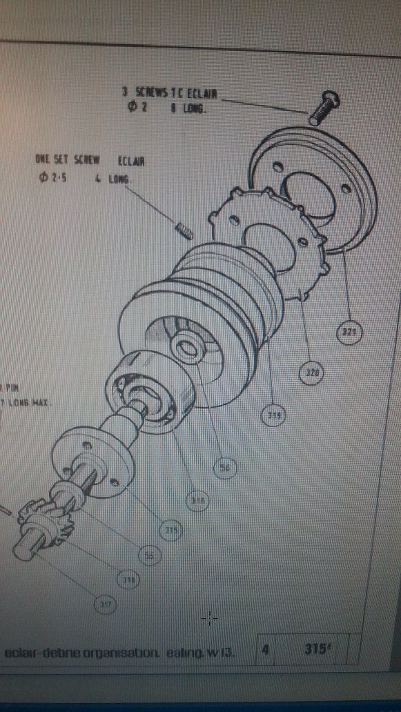
Just a clarification... The photo above showing the drive sprocket assembly, its from the Eng 400' mag. The drawing is from the Eng 200' mag. The sprocket drive hub on the Eng 200' mag, like the French 400' mag, has a V pulley machined into it for the take up "belt". The Eng 400' mag has instead a gear pressed on. That transmits to an idler or intermediate gear, then the take up arm spindle. Cautionary note...how easy it is to screw up... One of the sprocket drives, the detent in the shaft had burs from some prior rough treatment, that I did not properly debur. Fairly sure this damaged the brass bearing surface and maybe I damaged the shaft too. Lucky I had a spare mag wreck. A good example of not being observant and patient enough. The whole drive sprocket used to be a spare part. That would be quicker... Gregg. -
I know that comes off as a bit of a waffle. Can I sumarise that, or what might ensue.... We need a few well qualified, experienced techs globally. Let's find them, support them, helping source parts, offering parts that we don't need. Let's encourage education and share information to help those determined to learn. But, do service manuals need to be kept off the public domain to avoid a proliferation of DIY f--kups? It needs to be considered. But if there is a subculture of serious minded people trying to learn some of the tech they need to share and communicate. Need to unpick the issue of aged, contaminated lubricants. Same for the sintered bushes. Gregg. PS: Anyone new reading this will struggle to find the short list of qualified techs, so we need to insert an easily visible update occasionally, or put it in a separate thread. Also, maybe a separate thread for random servicing questions. And the "shit list" for bad boy techs is still a viable thing I say...
-
I can't re-activate my eBay account yet so not listed. Offers..?
-
Heikki wrote..lost the origin sorry... ..."If it's a camera body that would essentially lie unused due to dried, messy lubricants and you wouldn't send it overseas for servicing in any case, why not learn a bit about how it works, try to service it, learn as much as possible from different sources..." I may come off as one of the OCD ones, sorry. I'm basically like Heikki,but more cautious.. I'm a believer in doing for oneself and learning by doing, but I think with rare old cameras some learning and development of skills needs to come first. Otherwise, if DIY camera servicing becomes more popular, a significant proportion of the cameras in circulation will become compromised, and/hence the pool of used parts also. The age of lubricants is a major issue to unpick. Some proportion (perhaps most) of the cameras will never have had a full rebuild, so will still have some original lubricants in there, transformed by age and added contaminants into something akin to grinding paste. What proportion? Also, as mentioned before, the behaviour of the sintered bronze bushes with aged lubricant. So these need to be understood. We need a big change in attitude about keeping service history of cameras. It's natural to reach for advice from people experienced with servicing the camera type, but I don't believe they would all have the same technical opinion. Widen the field to include those techs working during the active history of the cameras...and there would be strata of service/skills from partial CLA to complete overhaul. The same idea applies now with the diminished pool of techs. Gregg.
-
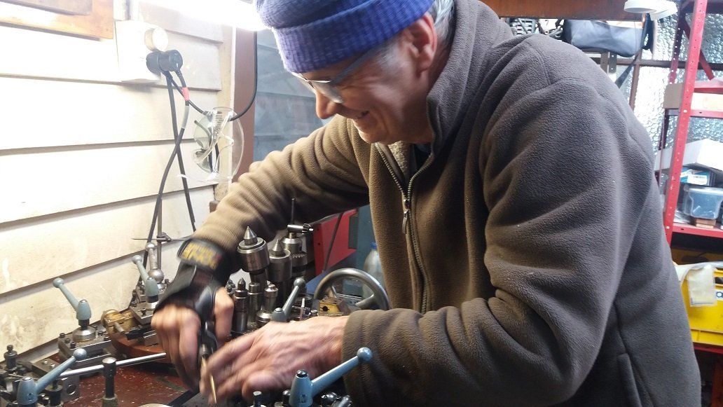
Re Heikki's post above...problem with the ACL movement...friction? The best you can get from someone like me on this is guesswork and ideas by inference from other things. Like I said before, what one doesn't know or understand about the engineering of the movement block can trip one up. One thing that will help, lets all agree to try to use the descriptive names (and numbers if it helps) for the parts, refering to the drawings. So for example the pic shows the claw control shaft. Can you make it clear what the symptoms are, what the problem is exactly? Are you noting high friction in a fully assembled movement block and can't see what's causing it? The only ideas that come to mind are..aged or contaminated lubricants, damaged bearing surfaces by scratches etc (I'm calling both contact surfaces, shaft and bush, bearing surfaces), misaligned bearing surfaces (by bent shaft or...). Like I mentioned before, the age of the lubricants may mean that a full tear down is needed. Guys like Paul S. and Dom J. would have some ideas on that. The aging of the lubricants may vary with temperature, humidity, frequency of use... The aging of the lubricant in the sintered bronze bushes concerns me. If that lubricant looses it's mechanical properties so that it doesn't self replenish the bearing surface when warm then the bearing isn't adequately lubricated. Do the pores become clogged? Simply adding oil near the juncture of the shaft and bush may not re-invigorate the original function of the impregnated "oil". If oil is applied externally to the shaft/bush juncture, then we need to know exactly what oil, roughly how much, how often and under what circumstances. Bruce at Arranda said that he only applied a drop of oil if the camera was sounding "rattley". Overfeeding oil to the sintered bronze bearing surfaces, if they are clogged with old lubricant, my instinct screams that this is bad, and you might have to do it frequently once the function of the sintered bush is compromised. The sintered bronze would behave more like a plain bush. Re the age difference between ACL I and II contributing to the age of the lubricants. If some lubricants have never been totally replaced since new, then the I vs II age difference is relatively unimportant. On the list of lubricants for ACL. I think we havent looked hard enough, or are asking the wrong people. We don't need exactly the same lubricants, but we do need ones with the same specified properties. Gregg.
-
English ACL 400' mags. Facts and Myths...
Gregg MacPherson replied to Gregg MacPherson's topic in Eclair
If the ball bearing is free then you could just leave it. The friction feeling could come just from the plain bearing, oui. Cant remember if my ball bearings were shielded one side or both. The side visible when looking down into the hub was shielded. I may still have the bearings and can check. The parts drawing shows no shield, but.... -
English ACL 400' mags. Facts and Myths...
Gregg MacPherson replied to Gregg MacPherson's topic in Eclair
More pics. First one, the blind bearing puller. We gave it a single split on the end, like a clothes peg. The llast one is the puller maker, Rogi...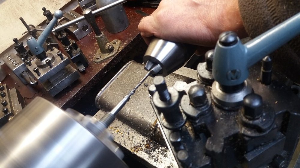
-
English ACL 400' mags. Facts and Myths...
Gregg MacPherson replied to Gregg MacPherson's topic in Eclair
Some pictures from the drive sprocket bearing replacement... Note that there are plastic spacer washers at either end, shown in the parts drawing as same, but they measured different thickness, so measure yours when they come out. The last picture is just in thanks to Rogi, who made the blind bearing puller on a Sunday...some pics follow in the next post. I improvised a puller to remove this brass hat by drilling 3 holes in a washer, 3 screws and a spacer tube that sat around the brass hat. The knurled knob for the drive sprocket (not shown) is fixed to the shaft with a screw. Before removing shaft from the assembly carefully debur the screw detent on the shaft.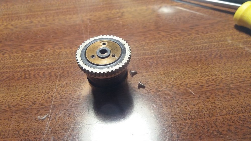
-
Eclair ACL English 400'magazines (two).
Gregg MacPherson replied to Gregg MacPherson's topic in Cine Marketplace
If anyone needs more information about the Eng 400' mags I started a thread on them English ACL 400' mags. Facts and Myths... https://cinematography.com/index.php?/forums/topic/91664-english-acl-400-mags-facts-and-myths/#comment-558877 Still waiting on re activating my eBay account so haven't listed yet... -
Anyone reading the English ACL 400' mags. Facts and Myths thread will have noticed Dom Jaeger's post. It looks like he is now servicing ACLs. When I asked him about it a while ago he wasn't keen because he was less familiar with them, but now maybe he's in. I think we can cautiously put a pin on Melbourne for our global map of techs servicing ACLs. We should do anything we can to support the techs. Find all the ex-Arts Media parts and locate other sources. If we have a stash of parts ourselves, like more than we need to service our own camera, or components for parting out (wrecking) consider making those parts available (to buy). Gregg.
-
English ACL 400' mags. Facts and Myths...
Gregg MacPherson replied to Gregg MacPherson's topic in Eclair
Hey Dom, I didn't really think you would mind. I was making a joke. I've seen your Cinetinkerer website with the Arri II teardown. I didn't make adequate notes or pictures when overhauling the mags, I realize that's a mistake now, it could save someone else some time. If you do have an English 400' mag job and are stuck I can try and remember. Maybe I should write it all down. Some important parts are common with or very similar to the French mags. I do have an Eng 400' mag here for parts, may help. And a few spare "rubber tyres". So, can we cautiously pin a flag on Melbourne, for our global map of techs who service ACLs..? Sweet. Last time this came up (some time ago) you were a bit cautious because you were less familiar with them. I always thought that a good tech familiar with SR and Aaton could bone up easily on ACL if he could have Q&A with an expert occasionally. Paul Scaglione recently said that he might help like that, if I read him correctly. There may be someone in Australia. Five years or so ago I was talking on the phone to a youngish sounding tech at one of the rental companies about servicing for Aaton and ACL. He was only familiar with Aaton, but a senior tech (I think in the same Co) was good with ACL. Can't remember their names, or the Co. Hopeless, I know... Anyway, there's a bit of a posse on the Eclair sub-forum trying to find suitable techs, you may have noticed. Still hoping to visit my sister near Melbourne, it which case I could drop off a set of S16 superspeeds, hoping you might check the focus lube on some or all, and swap the mounts out to PL. I'll PM about it later on. Cheers, Gregg. -
English ACL 400' mags. Facts and Myths...
Gregg MacPherson replied to Gregg MacPherson's topic in Eclair
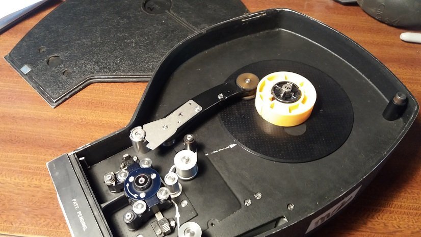
Forgot to include... Pic shows the take up arm in the retracted position. To engage, there is a round button on it's left end, simultaneously press and rotate that, holding the arm so it releases gently. The door won't close while the arm is retracted. -
You do? Who was the tech, do you know? Do I have to go on Faecesbook to find out? I never go there if I can help it.
-
Took ages but I started a thread... English ACL 400' mags. Facts and Myths... https://cinematography.com/index.php?/forums/topic/91664-english-acl-400-mags-facts-and-myths/ Oh, big letters, must be because it took ages to write...maybe I'm the one who needs to be given the antique typewriter (with no internet connection).....
-
[Edit: any added notes will be in brackets, just so] In the 80s, there (were) several ACL Is in use in Australasia ex Australian Broadcasting. People using them for documentaries, short films, music videos. They had the small original motor, the supposedly "non orientable" viewfinder (you orient the VF then rotate your head), English 400' mags, Angenieux zooms. I had one then. There is a lot of misinformation out there, some on otherwise quite legitimate websites, so I mean to question and clarify that...Please correct me if I make any factual errors. The Eng 400' mag design... Referring to the pic above..The Eng mag is the same design as the French except for the take up system [and some other small differences]. There is no friction drive belt to the take up spindle. Instead there is a take up arm with two rubber tyres on the brass wheels that ride on the take up roll, emulsion in, so riding on the cell side. The design gives a low current draw, on par with the original 200' mags, so was suitable for the small motor on ACL I. The mechanicals...There are gears that give the offset to the take up arms drive capstan. From there a toothed rubber belt goes to the rubber tyres spindle. I'll talk on longevity and servicing in a later paragraph. There is a large circular protrusion on the feed side that is the tension adjustment for the take up arm. The platter always seems to be 200'. Maybe the 400' ones did not exist yet. No matter, a properly serviced Eng 400' mag take up roll tracks true, even without anything touching the sides of the roll. The pressure plate was a single piece design, so the whole length of the plate is pressing the film onto the gate. Early French mags are the same. [ -The French mag doors seal just by having a double step on the edge. The Eng mag doors have a single step with a grey rubber seal mounted in a shallow chanel. The same grey rubber looks to be used for the Eng pressure plate light seal. Another difference, French/Eng is that the French mags have screw adjustments for the guide shoe clearance adjustment.] Servicing the Eng 400' mag So I crossed the line (sorry Dom) and did a full tear down on two mags. I had done a partial service on one previously, but this was a full disassemble, clean, repair/replace and lube. I didn't know anyone who serviced these. Bruce at Aranda was no longer into it when I talked to him a while ago. Maybe Les Bosher does, maybe Paul Scaglione at Visual Products (VP) could, but shipping is really high relative to the value of the mag. I don't know if Covid lockdown was the excuse, but I used generic synthetc lubricants. We still don't have a list of lubricants for the ACL... For the untrained, inexperienced person there's about as much work in overhauling one of these mags as in reconditioning an old engine. It needs the right skill set and intellect and a lot of patience. The ball bearing in the drive sprocket hubs was replaced. I think most of the mags here except the brand new 200' ones have some stiffness developing in the drive sprocket bearing. Replacing was detailed, but yields to patience, straining my memory now, a puller was improvised to remove the brass hat shape at one end and a blind bearing puller was made so I could pull the ball bearing out. My friend made one for me, but the ones you can buy should work ok. The likely service intervals for different parts (sporadic rather than everyday use)... After 40 years everything needs CLA. Normally, the oblique drive shaft bearings is down to the longevity of the grease. Once or twice in a mags lifetime...Plain bearings that are loaded, a shorter interval, they will be checked whith the camera's CLA. The drive sprocket has a plain bearing and a ball bearing. The shielded ball bearing, replacement once or twice in it's lifetime. The plain bearing will need clean and lube more often. The friction is easy to assess at CLA time. Obviously, plain bearing surfaces that are loaded and rotating need care with checking at CLA time. A good calmera tech who's seen the mag before will save you money. The toothed rubber drive belts for the take up arm seem fine after 40 years in the Auckland climate. Other climates may shorten their life. One can often find fine pitch belts, or have them made, but I think parts from wrecks will cover this need if it ever arises. The little rubber drive wheels may have a life span of a few years. I had some made, cost me $1 each, needing a tiny bit of hand finishing on the edge. The light seal at the pressure plate and mag doors (look like the same sectional shape) seem ok for the life of the mag unless someone damages them. The, English seals, grey, a hollow tube or D section, look better to me than the French pressure plate seal, black, solid maybe. One can buy a 2mm diameter hollow rubber section dirt cheap on eBay and replace if needed. Paul S at VP thought so For the pressure plate seal I'll wait and see if it gets around the corners without a crease. For the mag doors I think the bend radius is fine and a crease in the corner is ok. Current draw, French 400' vs Eng 400' vs 200' mags, test results, facts vs myth... Years ago I tested the current draw on my ACL I with loaded 400' mag, 25fps, and got 1A. It was regularly serviced by a good tech. I did have him switch to sub zero grease around then for a short time, and I can't remember if I did the test with that grease in. Temperature for test, guessing 22degC. The only camera available for the test now was an ACL II with latest motor, basically almost brand new, and with the tuning for noise at VP the amps can go up a bit. Current draw with no mag, 1A. So the amps raw data may be high and misleading, but the comparative will be meaningful. I'll show that, the % change in current draw...Another issue, one that may compromise the test...I chose from three French mags the one with least friction. Mags lightly used, no service history. The fingerometer tells me that friction is slightly higher than the brand new 200' mag. 200' mag...0%...is the baseline. French 400'(Pat 2)... +39% Eng 400' (mag3)...... +6% Eng 400' (mag2)...... -6% (Edit: Took about 5 readings over 400'. There was a small increase in current draw as take up size increased. Summary is taken from max values) So I hope this illuminates the issue about the English 400' mags and the small motor. Of course, we haven't yet measured the current draw on a serviced French mag yet. I could have done that before I sold a couple to Heikki a short while ago. Heikki, if you get the urge, I'm happy to help set up the experiment. Otherwise, I will eventually overhaul the French mags here. Untill we do, test a freshly serviced French 400' mag, it is possible that the French mags are OK on the small motor. It will need to show the same amps as a 200' mag to convince me. I knew some guys that blew their ACL I motor with a French mag. I bought their second camera, with English magazine. Cameras were regularly serviced back then, but I don't know if their French mag was. Other myths about the English 400' mag... I think I read on Ermut's website that the Eng mag was prone to film jams. This is a complete myth and jams will only happen with really gross lack of service. I can illustrate with my own example...Bought an ACL I with Eng mag about 1984. The camera body was regularly serviced, but the mag not. The rubber take up tyres were slipping on the wheels. Tyres didn't look old, but maybe the wrong size ID. Result was poor tracking on the take up and sometimes a "loose wind" going to the lab. Young and not yet clever, I fixed it by improvising guide bars on the mag face and door (platters are 200'). Years later I just replaced the tyres and it tracked perfect and tight. That myth needs to disappear.....!! Final thought, make sure your loader is properly familiar. English 400' mags have a spring loaded column on the feed side. Threading around that grossly scratches the roll. My arri-familiar but new to ACL producer once helped out and did that for me (horrific scratches on the film). Gregg.
-
I've had two of the English mags that were ex single system sound, the sound module no longer there and the entry hole at the bottom of the casting with a plate over it. Welded I think. I did some testing on relative current draw on French vs Eng 400' mags recently and will start a thread on that. Stephen Jackson recently advertised his ACL with small motor and French 400' on the forum and sold it. After some discussions with him privately on the issue. Apparently he had it serviced, and the tech, who he would not disclose, told him that the strain on the small motor was a myth. See you over there maybe....English ACL 400' mags. Facts and Myths...