Duncan Brown
-
Posts
550 -
Joined
-
Last visited
Everything posted by Duncan Brown
-
Questions that immediately come to mind: -- The main motor model - if it uses none of the camera's electronics, does it have its own on/off switch? And will that mean that standard ACL things like the grip with switch, or the built in light meter, are no longer functional? And if that's the case, does the customized model retain any of that functionality? -- Will the external precision speed controller be compatible with any of the existing standard ones? (I have a Tobin milliframe controller, so of course I'd vote for that one!) Thanks, Duncan
-
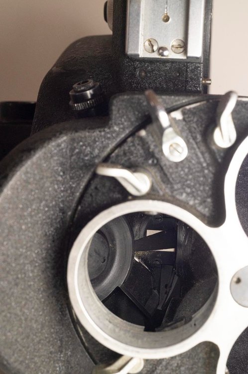
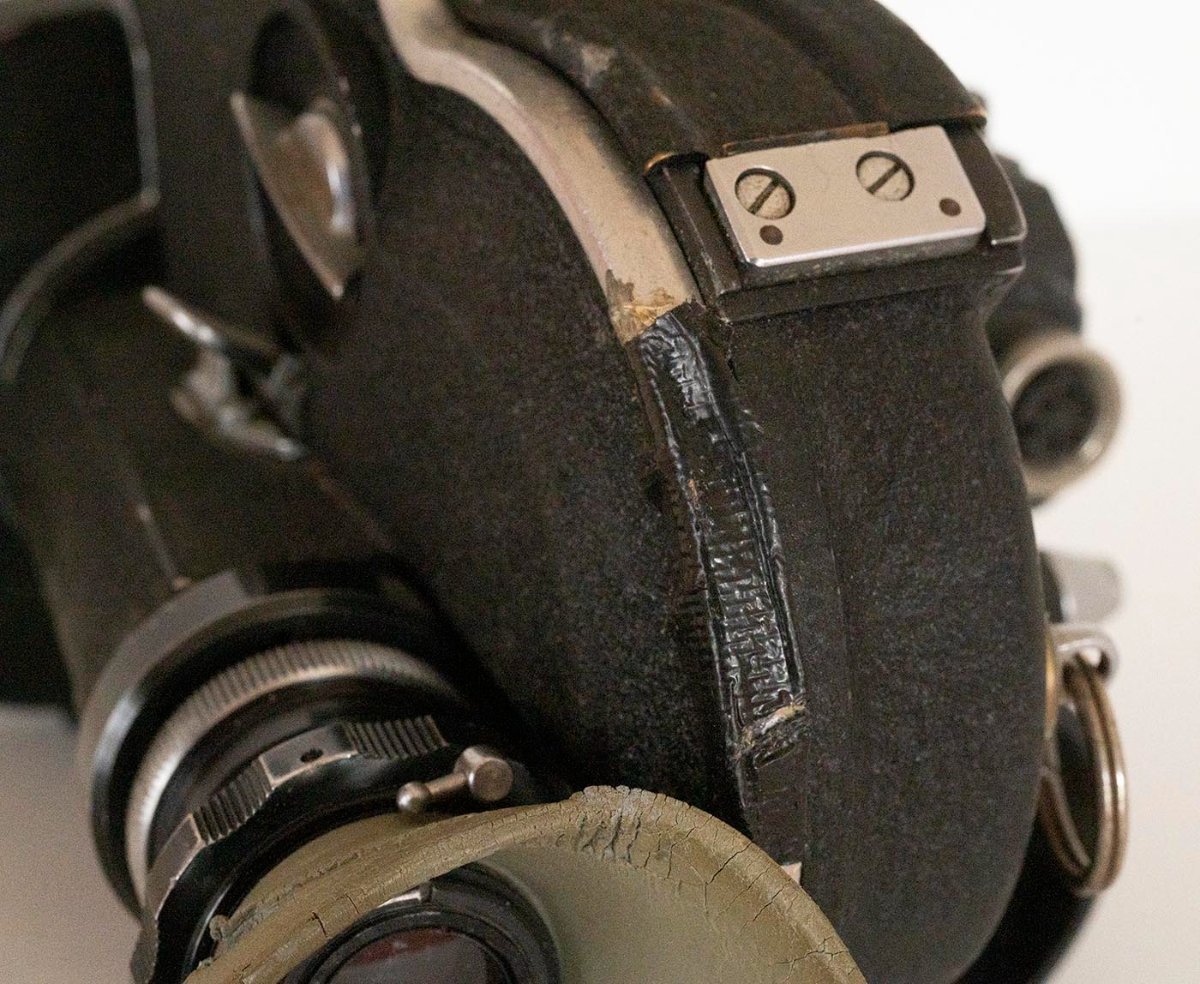
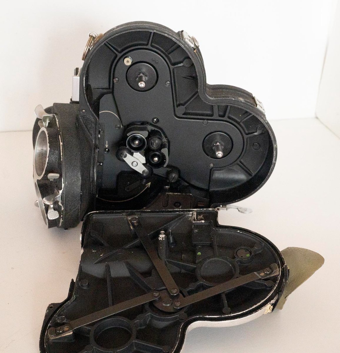
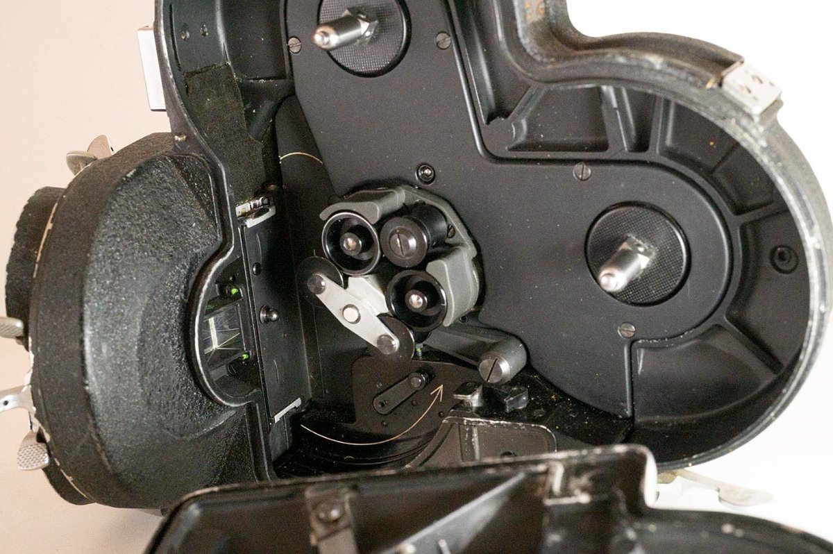
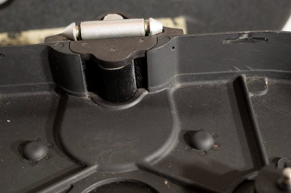
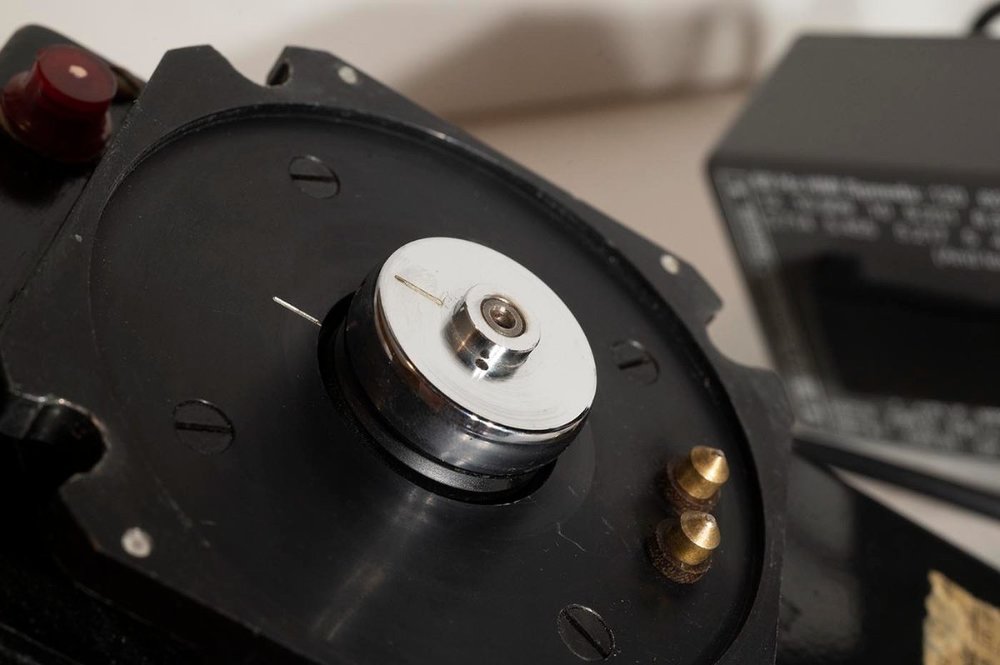
Is it my imagination, or is everything in your first disassembly picture fairly coated with corrosion? Bad sealing design? Bad storage? For some reason, people like to stash old no longer needed cameras away in very wet environments, so when they come out decades later and go to an estate sale and then ebay, with everyone just assuming it might work, you end up discovering everything coated with green and brown fuzz. It's why I'm such a lowballer on untested cameras on ebay., especially when they only have a couple of crummy pictures. Duncan
-
I put this on eBay now, in case for some odd reason you would prefer to do it that way. (As usual, make a cheaper offer and mention you are from cinemtography.com and I'll be more willing to cut a deal!) Duncan
-
Arri 16S for parts or repair - $400
Duncan Brown replied to Duncan Brown's topic in Cine Marketplace
For those keeping score, I accepted a $375 offer for it on ebay. Duncan -
Securing an Arri Standard lens to Arriflex 16BL
Duncan Brown replied to Diego Collado's topic in ARRI
Doesn't the 16BL have a whole housing around each lens? As you can tell I'm not that familiar with it, or if you can change lenses within a housing, or anything. I know the 16S and 16M both take those lenses. ...but the way you generally mount an Arri Standard Mount lens (ARRI-S), which is what you have pictured, is to first line up the tab inside the mount with the slot around the perimeter of the back of the lens... then push the lens in until it stops... then squeeze together two little levers at the lens mount hole, which will allow you to shove the lens in a little bit farther... then release your squeeze on the little levers, and the lens will be locked in place. The levers pull away little pins, which allow the lens to push into the mount farther, and when you release the levers the pins extend back into place, landing in that groove that goes all around the outside back of the lens mount, securing it in the mount. (Now does any of that match up with anything on your camera?) Duncan -
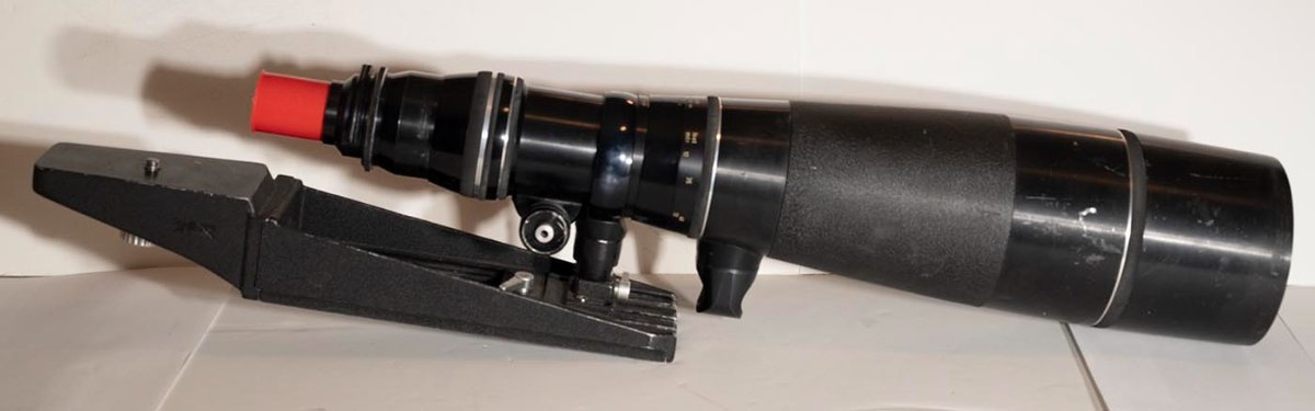
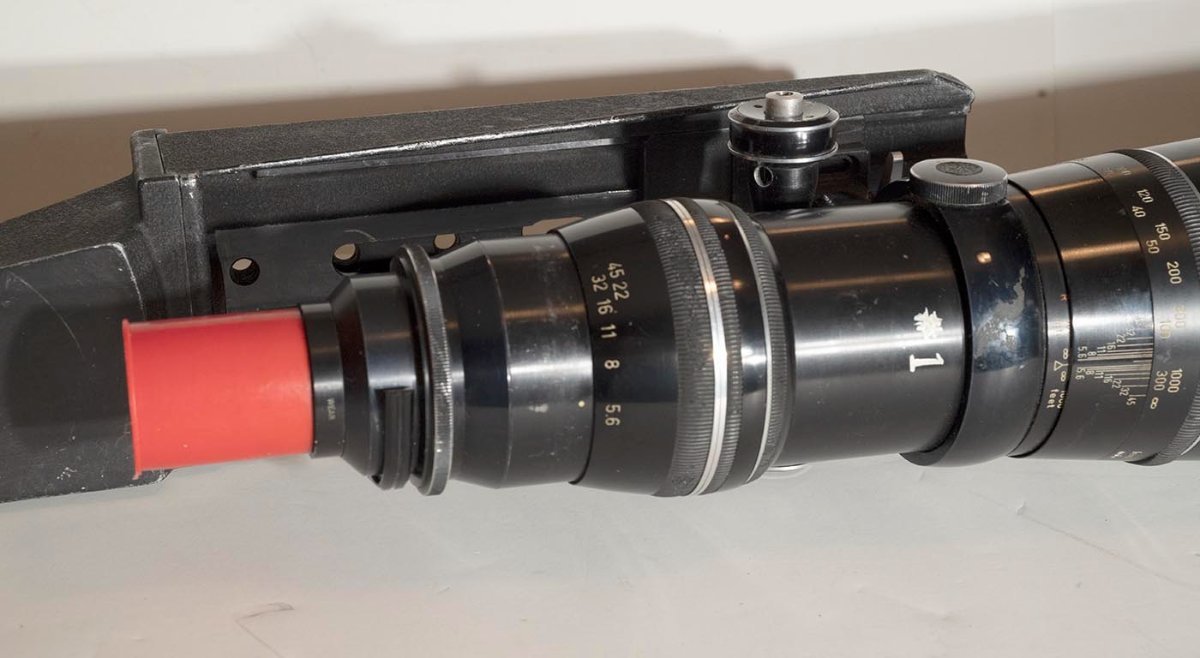
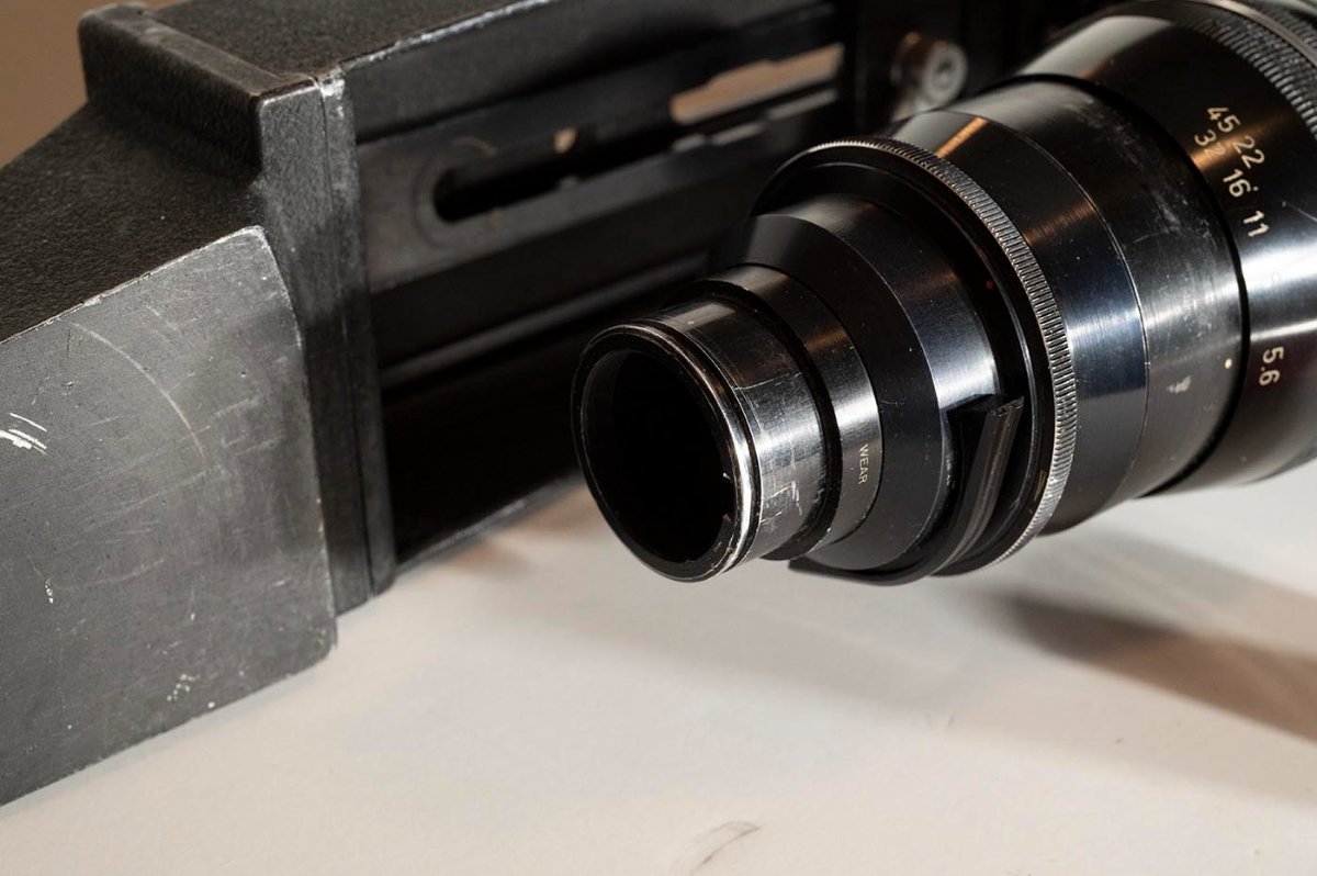
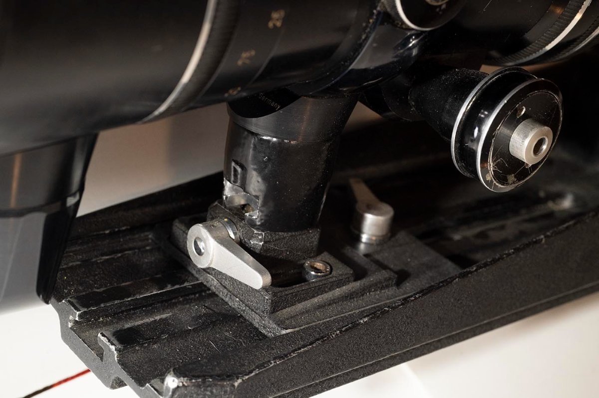
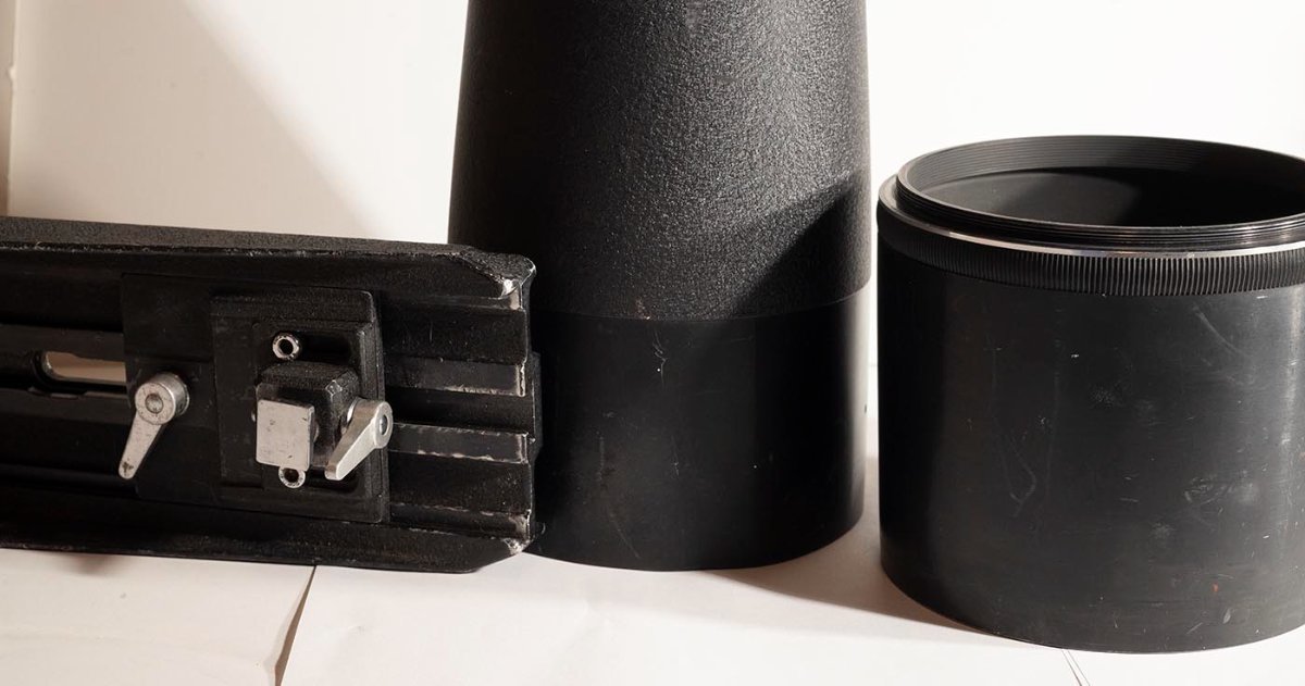
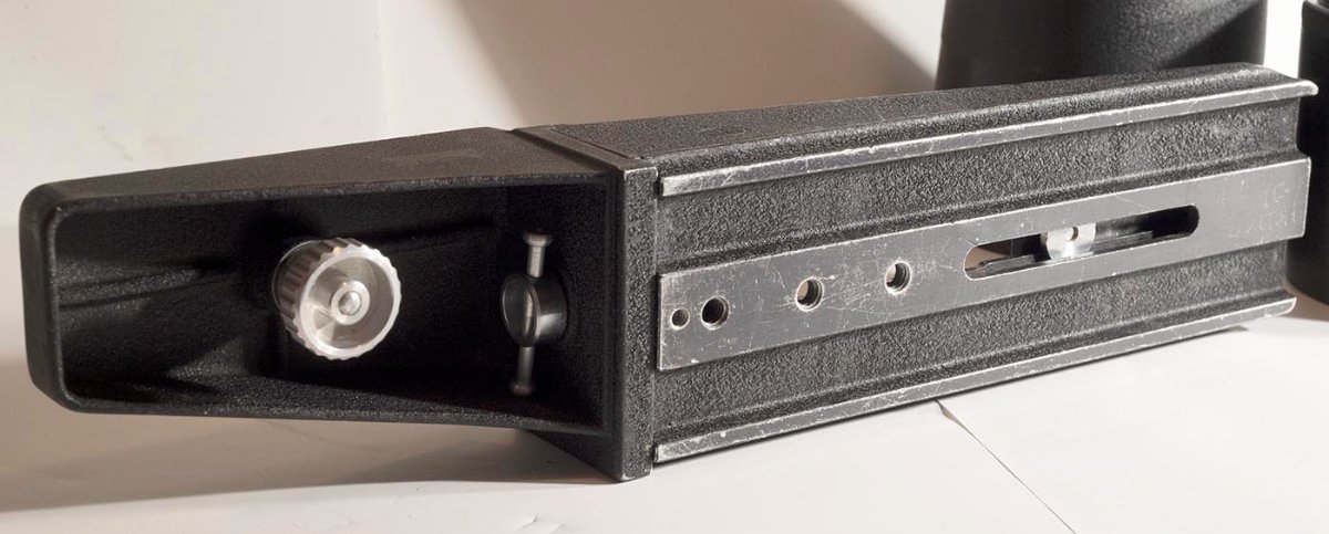
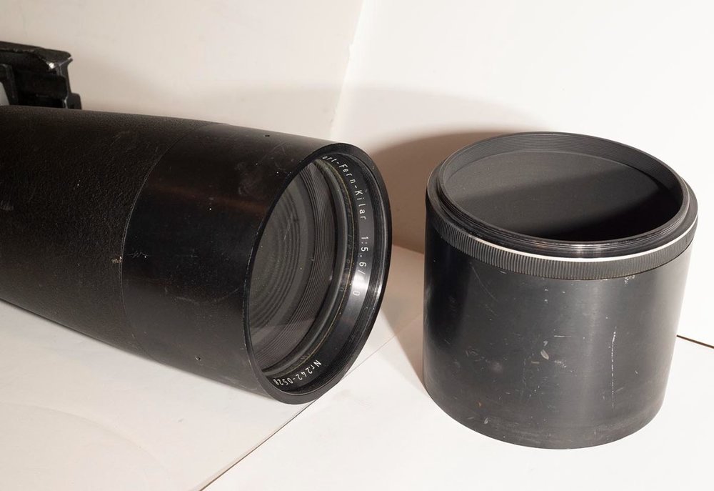
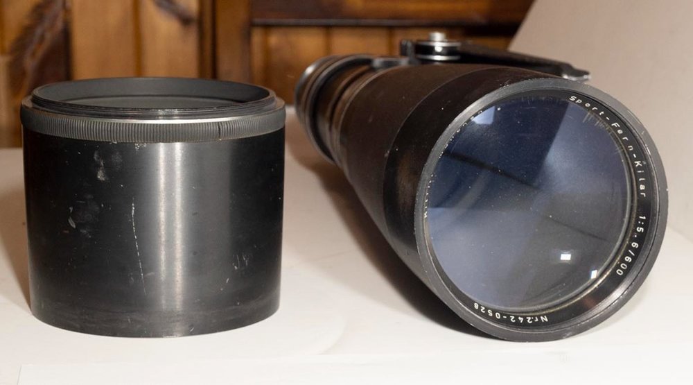
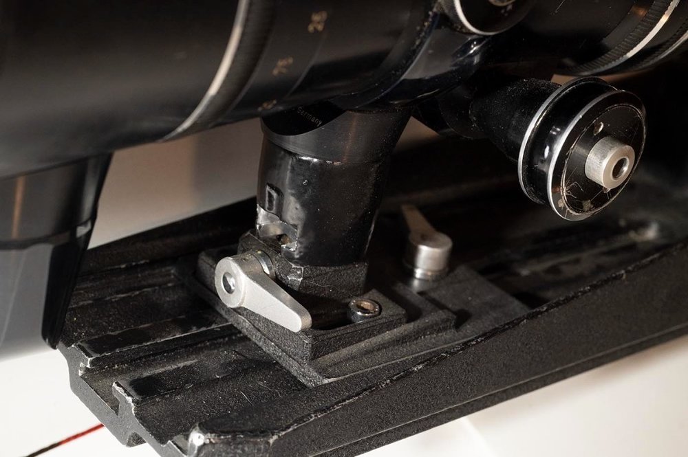
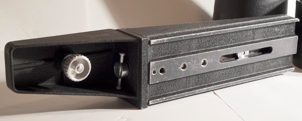
I've decided this is just too much lens for me, but I did successfully gather together all the parts to make it actually usable with an Arri 16S (and probably some other Arri-S mount cameras too.) Includes the lens, original hood, and Arri long lens cradle with all the bits to line up and lash together a 16S and this lens and mount it to a tripod (see last picture - 16S not included in this sale!) It's certainly seen its share of banging around over the years but everything is straight and functional. There's a little dust inside the front (only) element, which obviously doesn't show up on film. It's also got the usual bit of striations in the coating or whatever around the outside of the element but again, not going to affect the image way out there. The cradle is currently all set up for a 16S to drop right in there, but it's completely adjustable in many dimensions and should be able to fit about any camera with an Arri-S mount. There's a UV filter in the holder. Focus rack is silky smooth - too smooth, you have to be careful handling the lens before it's all bolted together, so it doesn't rack itself from one end to the other while you're not watching. I'd like to get $1000 for the complete rig; not willing to separate the cradle from the lens (though if it doesn't sell I'll eventually consider that.) Let's call it $50 shipping in the US, and I'll probably pay more than that - it's a beast! Exact shipping costs elsewhere in the world, but it won't be cheap! Duncan


-
Arri 16S for parts or repair - $400
Duncan Brown replied to Duncan Brown's topic in Cine Marketplace
Haha I'm a moron. I just used this body to test a magazine with motor I'm selling... and the tach works just fine. I bet I had the motor in reverse when I tested it before. DUH. (In case that was what was keeping you from buying it!) Duncan -
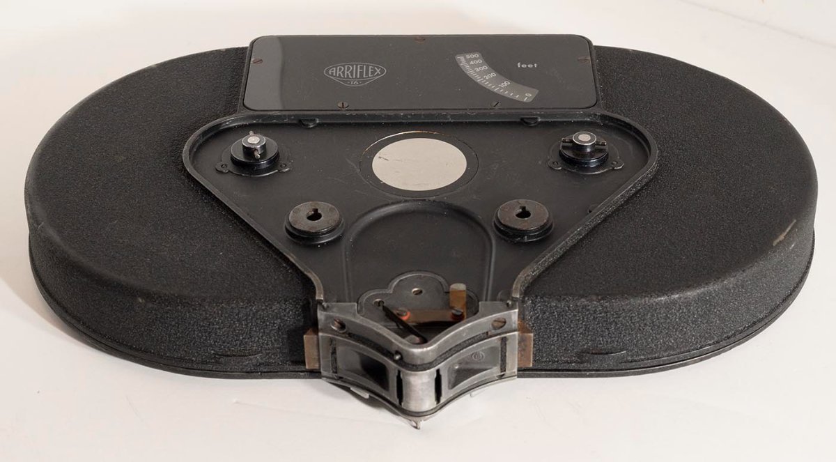
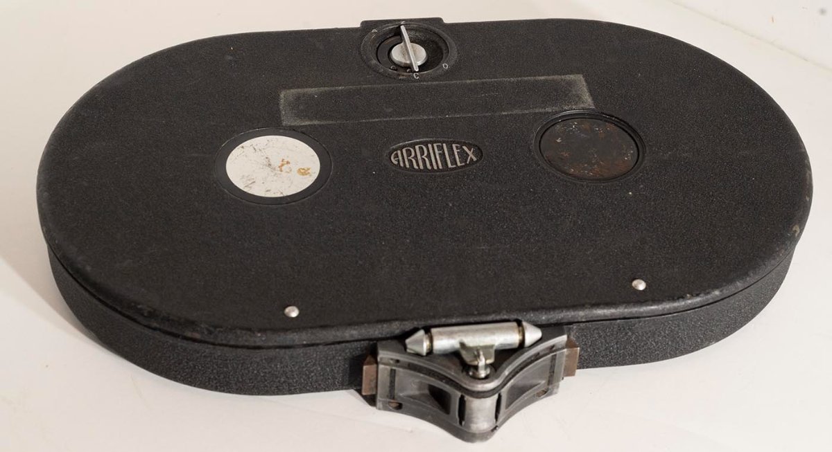
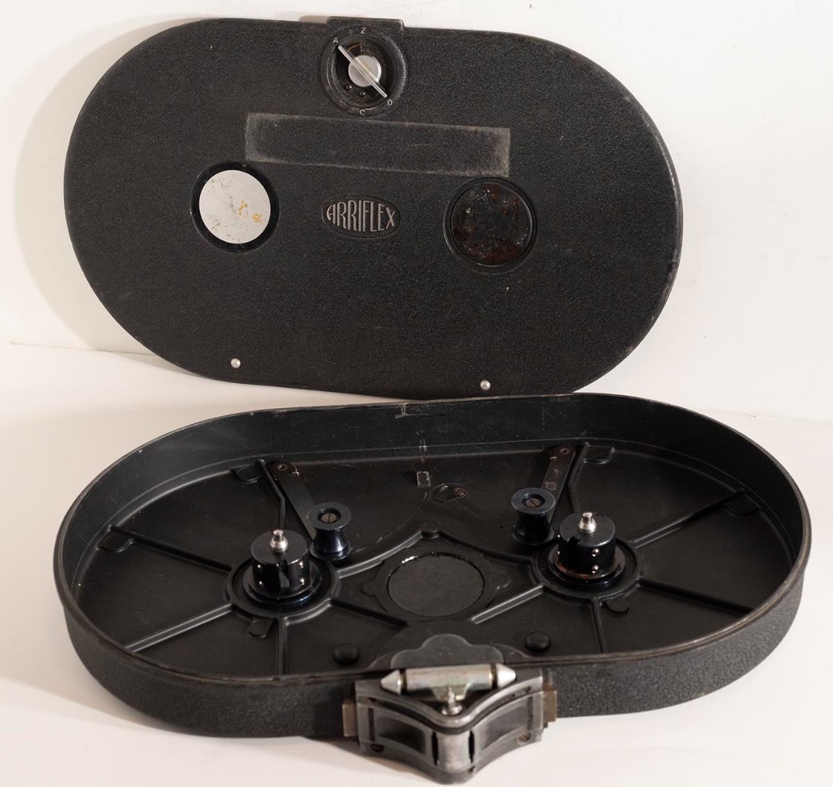
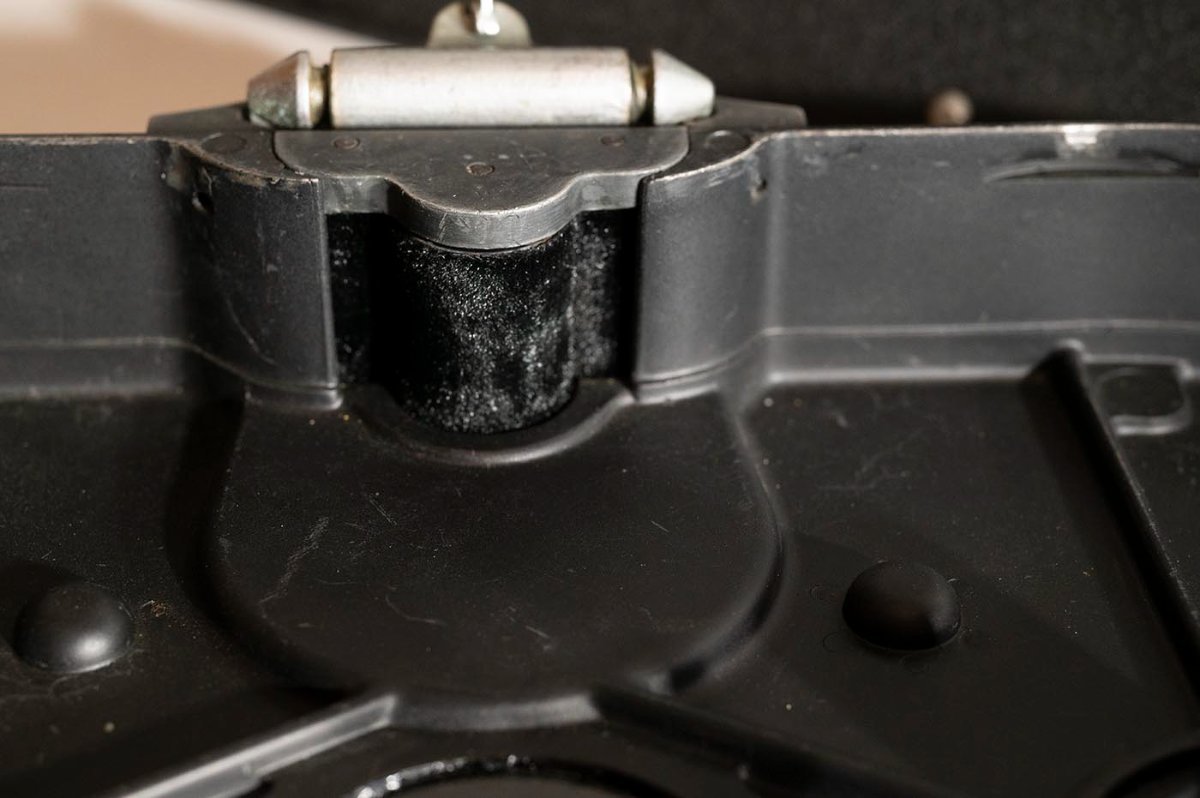
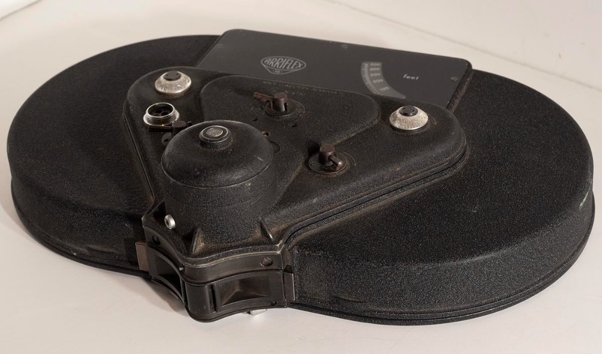
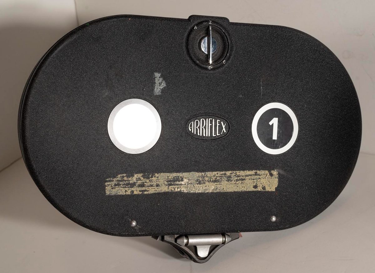
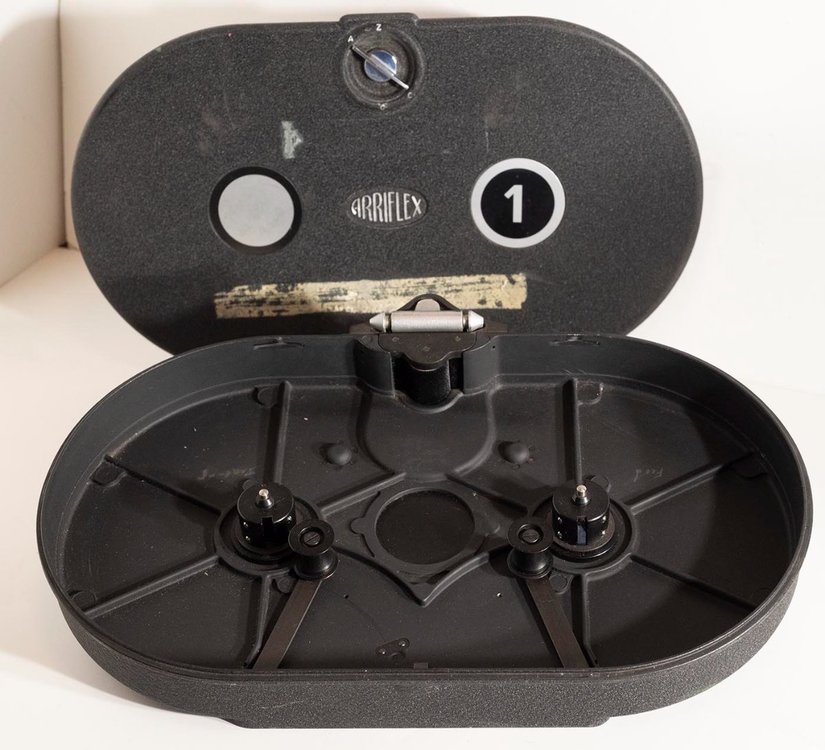
I own too many thing, trying to shed a few. Here's a nice Arri 16S 400' mag with 8V motor, plus another magazine. The motor works (I just tested it!), the mags both spin freely on both hubs, all core adapters are present, the felt rollers all look intact and fuzzy, etc. They could probably use a good cleaning inside before use, as they've obviously been kicking around for years, but other than that they're ready to roll. I'd like to get $150 for the magazine with motor, and $75 for the one without. If you buy it all together, let's call it $200 even. $30 shipping in the US, or whatever it actually costs anywhere else in the world. (Postage costs are getting crazy but I'll do it if you'll pay for it.) Duncan In this post is the one with the motor. In the next post will be the one without.


-
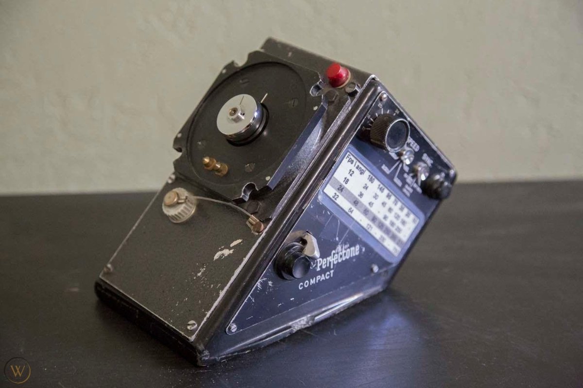
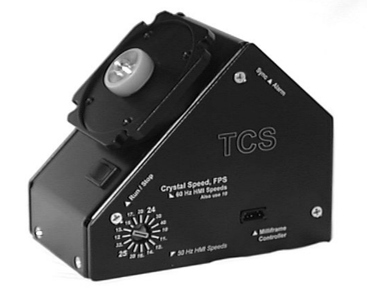
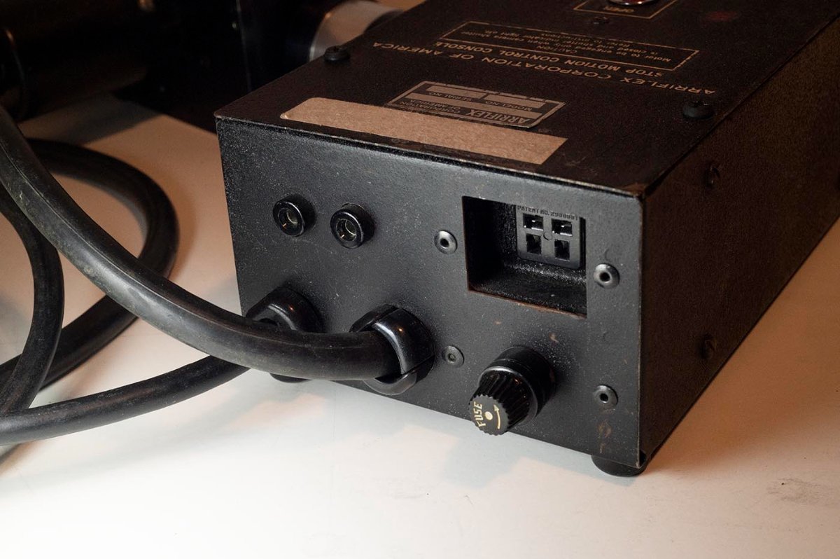
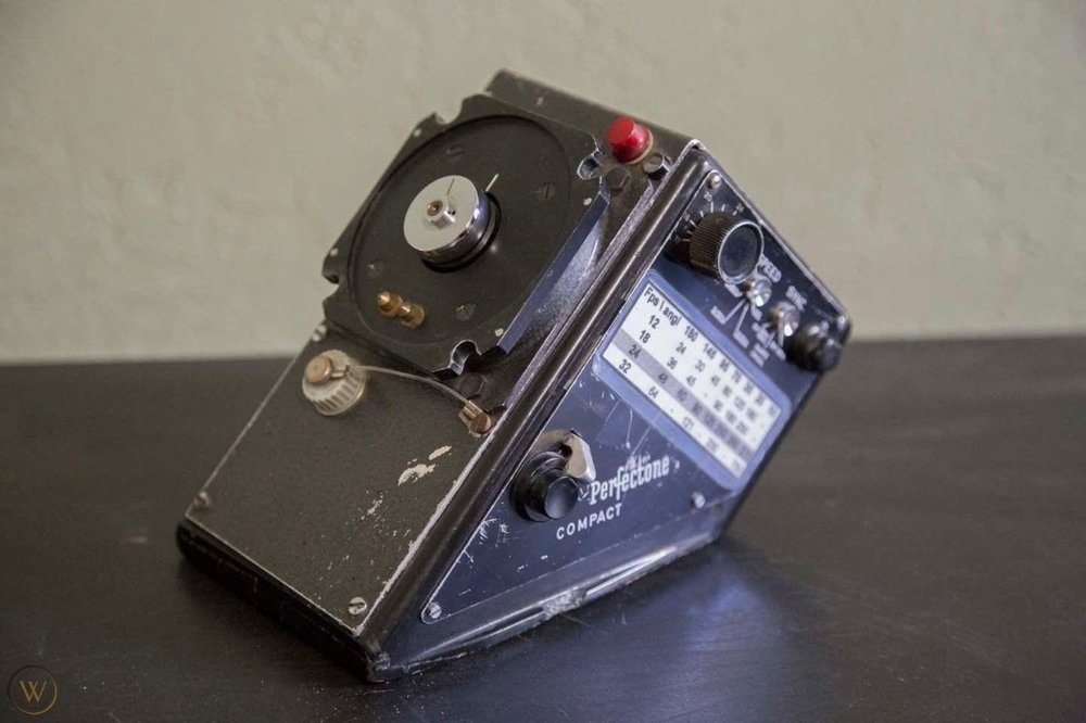
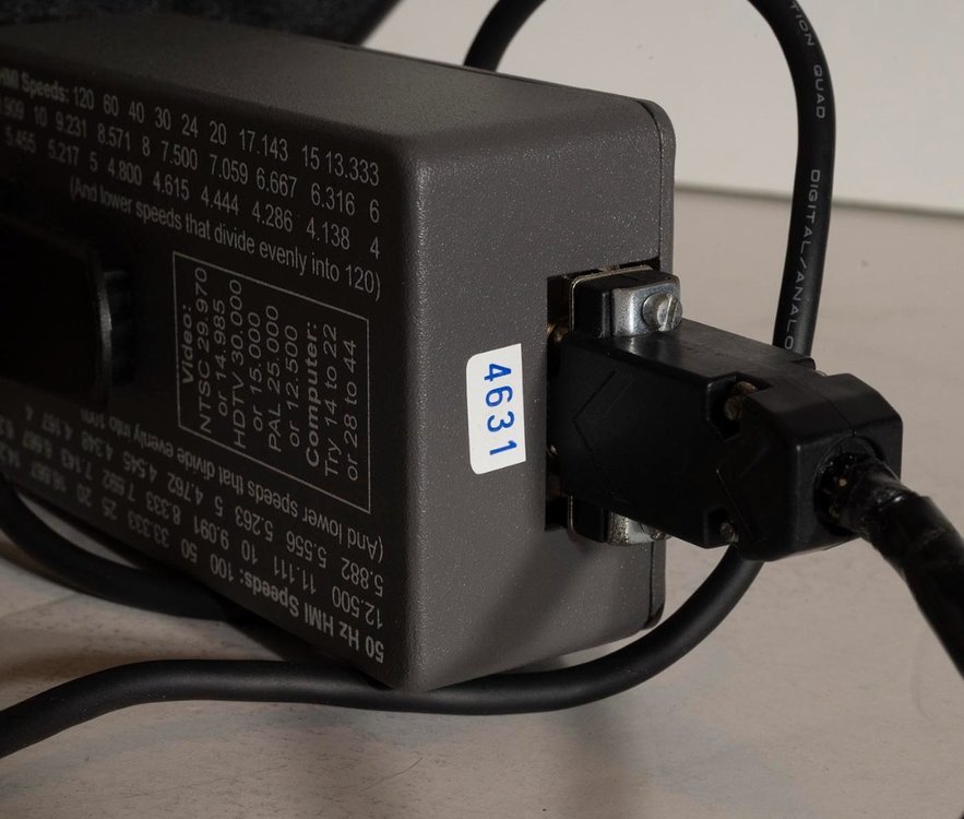
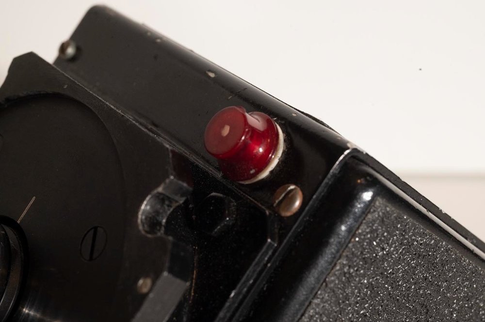
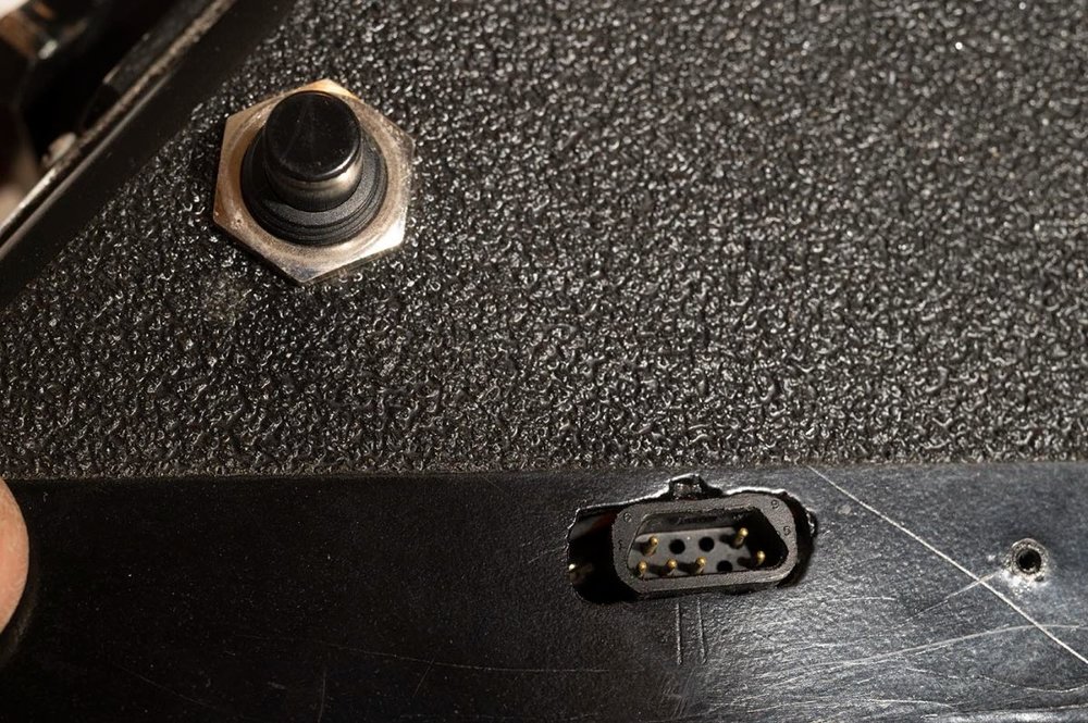
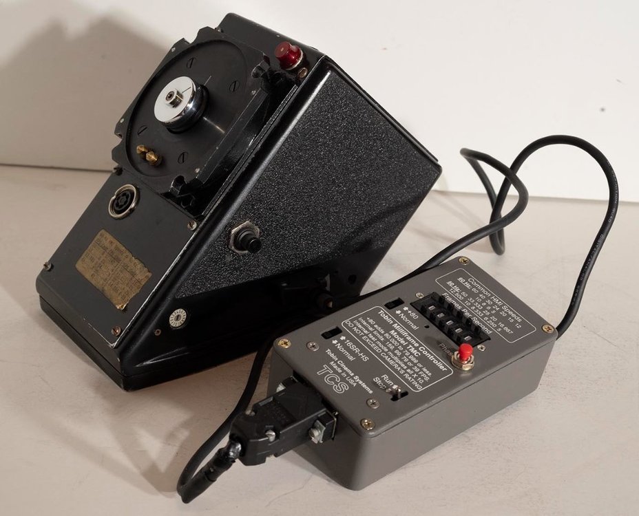
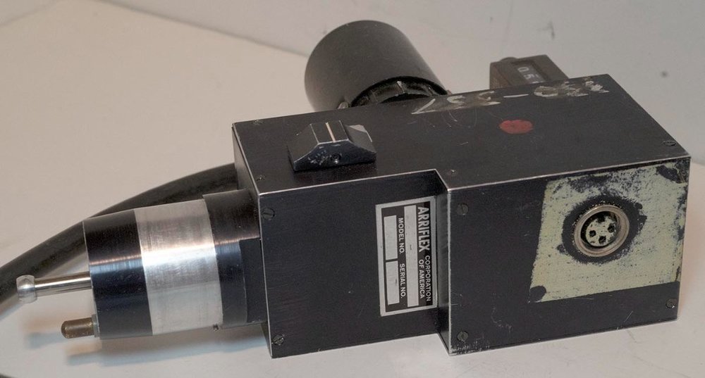
I just noticed that the (plastic?) main case looks exactly like the Perfectone Compact motor! Did Tobin borrow one of those to experiment with? Originally source their cases from Perfectone so as not to incur duplicative engineering costs? Or did Perfectone mess around with making a motor that would take the Tobin controller? Very curious. Anyone have one of those that they could take more pictures of? Clearly the Perfectone has a LOT more going on on the side panel than this one, but the red light and the button are in the right places. Would be interesting to see if the bottom surface matches up. Duncan
-
More eclair literature scans. I'll also send them to the Eclair website. ACL I instruction manual: http://backglass.org/duncan/eclair/eclair_acl_i_owners_manual.pdf ACL 1.5-ish brochure http://backglass.org/duncan/eclair/eclair_acl_brochure_02.pdf ACL 1.5-ish 1976 price list: http://backglass.org/duncan/eclair/eclair_acl_price_list_19760301.pdf As usual, the crummier 100dpi scans but smaller files sizes: http://backglass.org/duncan/eclair/eclair_acl_i_owners_manual_100.pdf http://backglass.org/duncan/eclair/eclair_acl_brochure_02_100.pdf http://backglass.org/duncan/eclair/eclair_acl_price_list_19760301_100.pdf Duncan
-
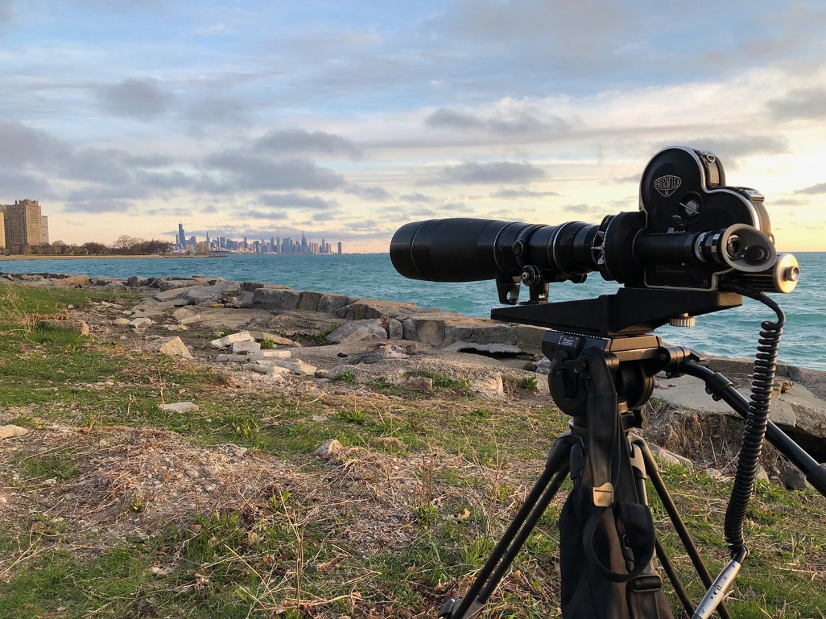
I've been shooting some test footage on several NPR bodies, including this one, so once I finish up that film and get it processed and scanned, I should have some better idea of how well the normal/Super 16 switchability works in terms of the viewfinder framing, etc. (I've just been moving the magazine filled with 400' of film from camera to camera.) The film I used for this was some badly outdated 250D - double perf even! - so it will make for some lousy footage, but should provide some useful frame grabs in terms of scoping out what I wanted to see about this camera. Duncan
-
Eclair Flea Market
Duncan Brown replied to Gregg MacPherson's topic in Marketplace Listings Under $200 / €200
Hey look there's a nice NPR on ebay! Oh right, it's mine. I've been buying too many of them, time to de-hoard a bit. https://www.ebay.com/itm/255562503204 As always, use the "Make offer" option and include a comment that you are on these forums and I'll be more willing to accept your lowball offer ? Duncan -
Oh, and assuming that milliframe controller is accurate, it proves that tachometer app I have on my phone is dead on! The controller goes to 3 places after the decimal point and the app only does two, but they match up precisely. (When using the tachometer app to dial in on the speed of the camera mirror while running on the milliframe controller.) Duncan
-
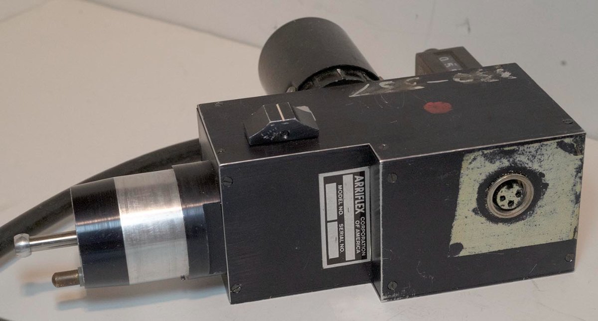
This bizarre video, which claims to show a TXM-14, definitely shares more details with my motor, than that stock glamour shot of the motor I led off with. Duncan
-


-


-
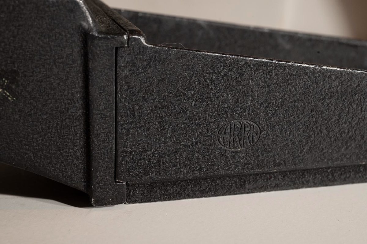
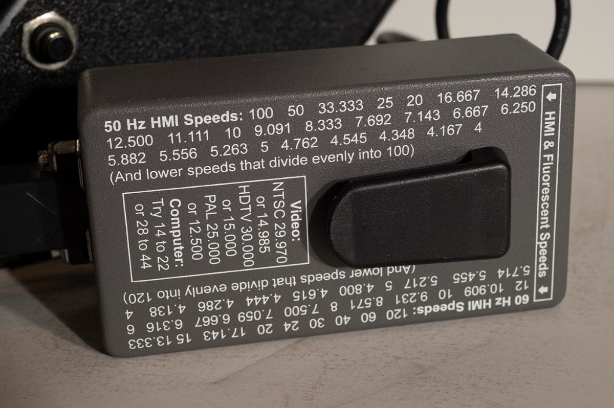
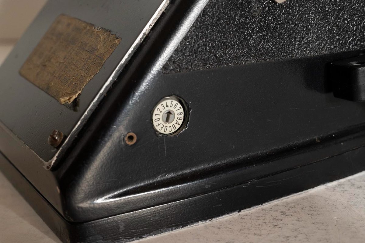
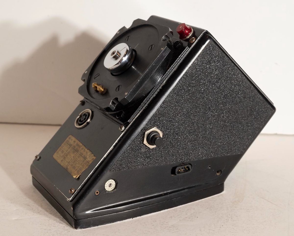
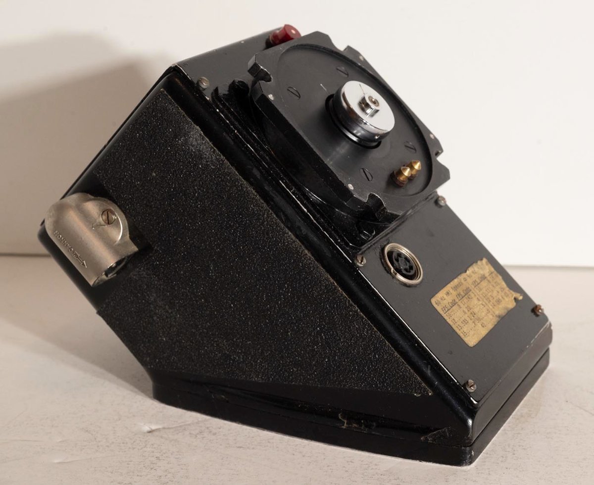
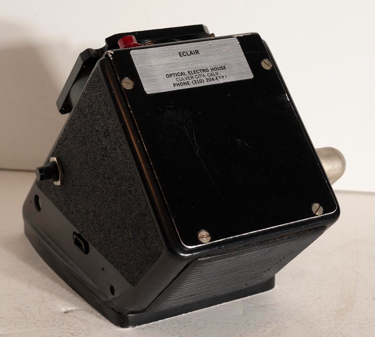
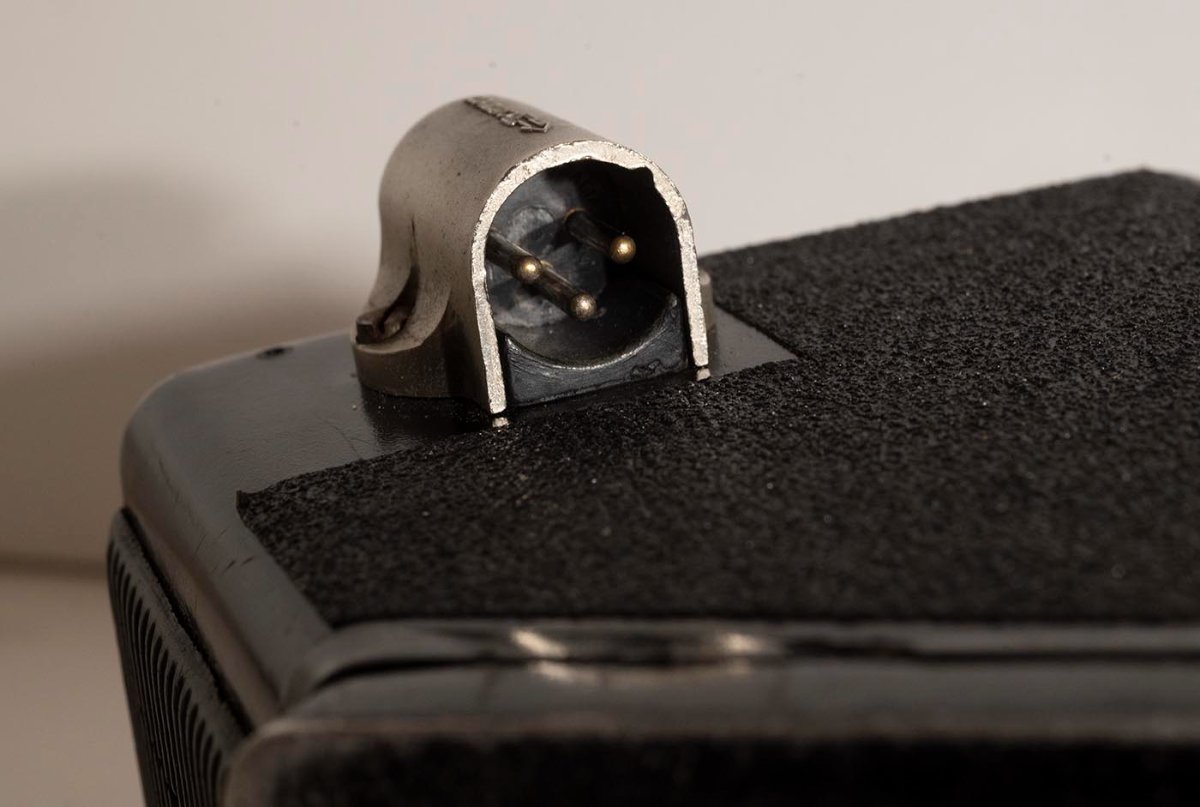
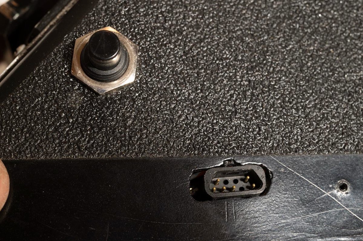
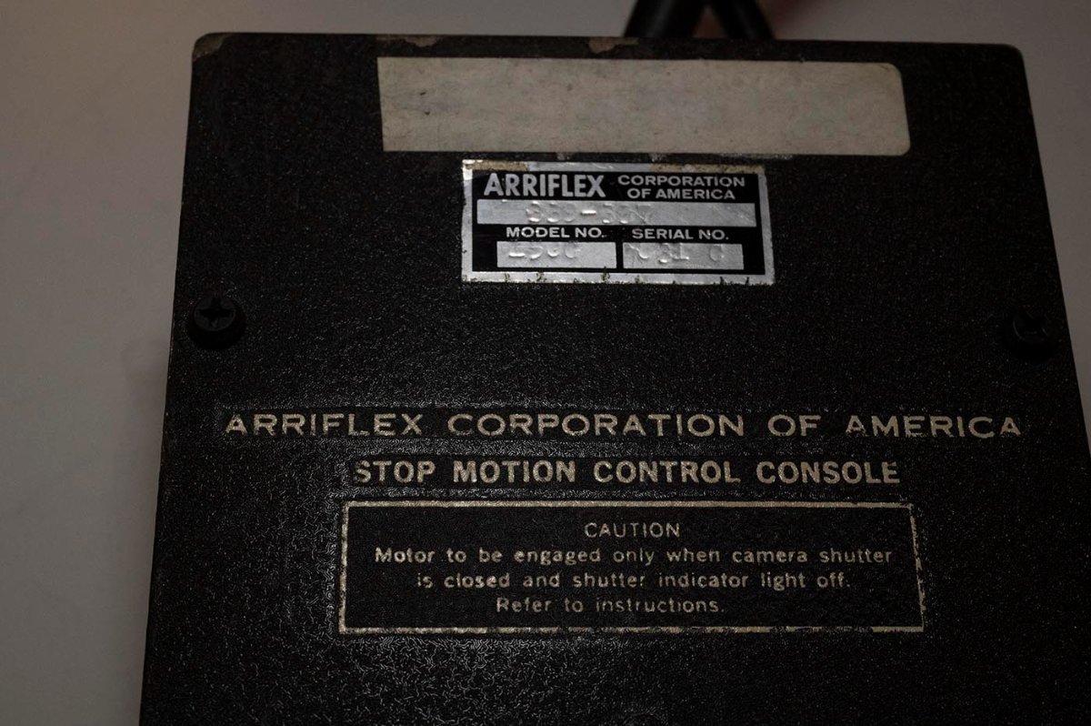
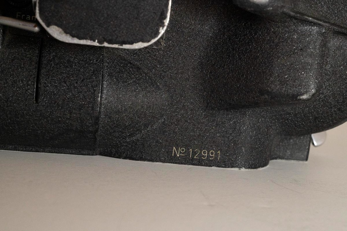
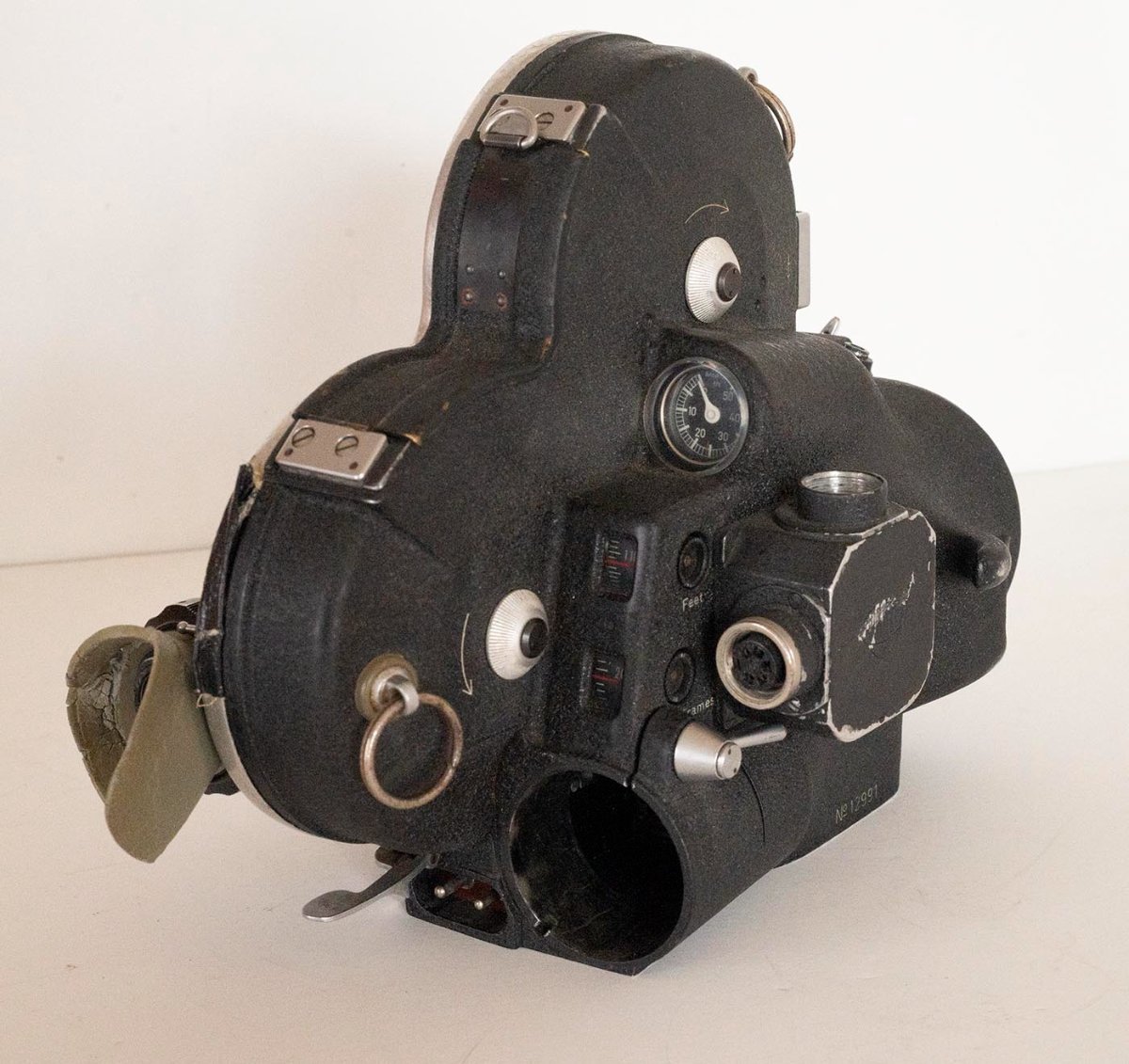
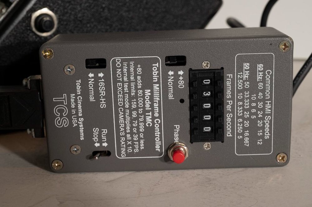
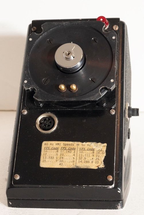
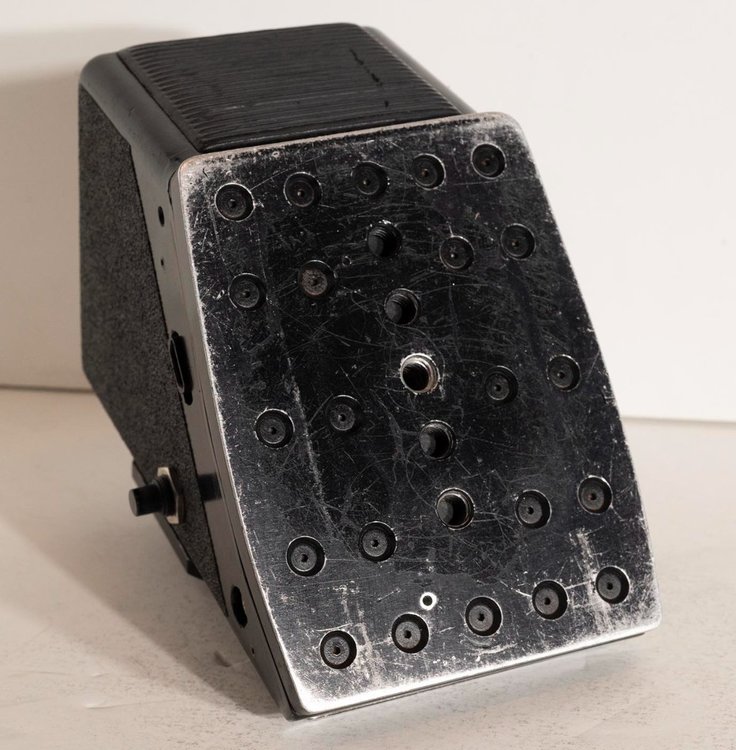
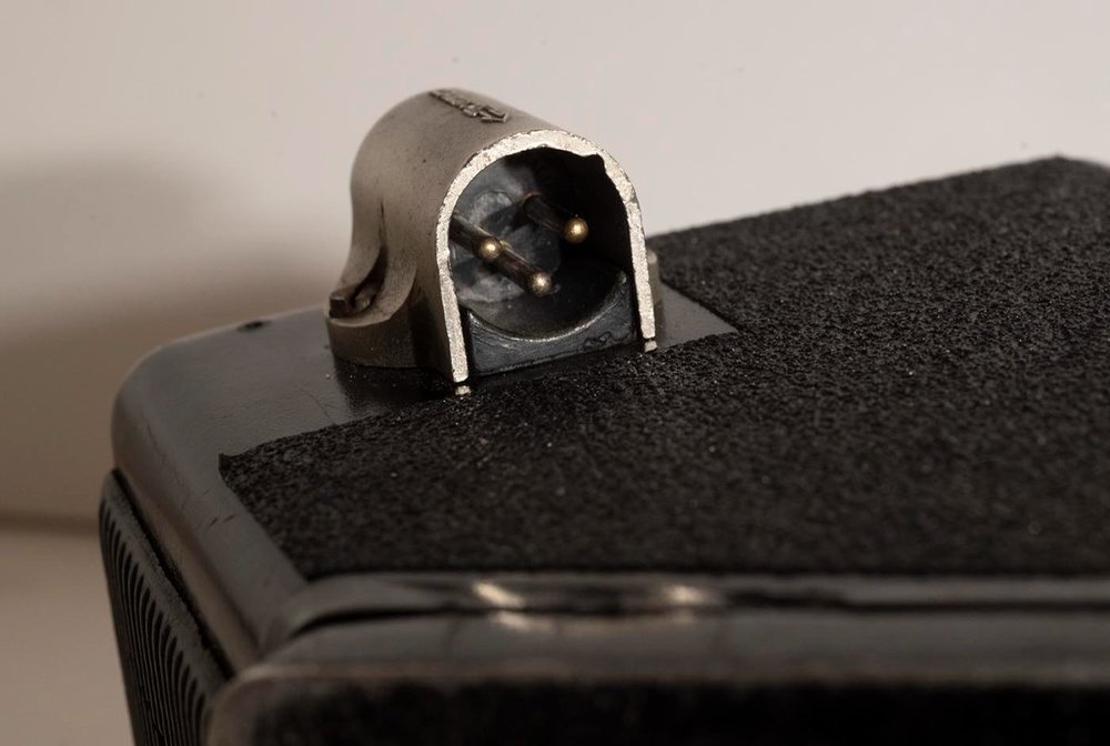
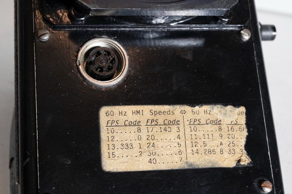
This guy shows a staggering number of different motors available for the NPR: http://www.tfgtransfer.com/motors.htm Well I recently stumbled across one that isn't exactly any of those...though maybe it was an early prototype of the Tobin TXM-14. Or maybe a clone of it? If I google the Tobin NPR motor no two I find are the same, so the product definitely went through some evolution! But mine is the least polished of them all. Crudely hand-cut holes in the plastic case for connectors, that sort of thing. It has an Optical Electro House sticker on it, but I think that's just because they serviced this camera (from other clues I found), not because they made the motor. (As an aside, from what I've read about Optical Electro House, Eclair owners are far worse off for that guy having retired years ago - anyone know if someone picked up his parts and tools and knowledge?) I'll start with a picture of the real Tobin motor I stole from the internet, then in additional posts I'll add pictures of my motor to compare. It seems to work flawlessly, and might actually be even lighter than the Alcan, though certainly not as elegant looking. It's just a wedge shaped box. Duncan

-
Dropped the price to $300 on ebay, and it sold pretty quickly thereafter. Duncan
-
Zeiss 8mm, T2.1, Arri-B mount, with PL mount. For 16mm.
Duncan Brown replied to Gregg MacPherson's topic in Cine Marketplace
That's weird - I have what looks to be an older version of that lens (Distagon 8mm f/2 but not the T* designation and the barrel is the same diameter the whole way, it doesn't flare out at the front) and it's not even close to vignetting on S16, at least as far as I can tell in my viewfinder. I can see the vignette out at the fr corners of the whole wide NPR viewfinder field of view, but nowhere near the framing lines. (So I was assuming it was a legit S16 lens...) Duncan -
Eclair ACL, sintered bronze bushes lubrication....
Duncan Brown replied to Gregg MacPherson's topic in Eclair
Good stuff Gregg! Thanks for chasing that down. Duncan -
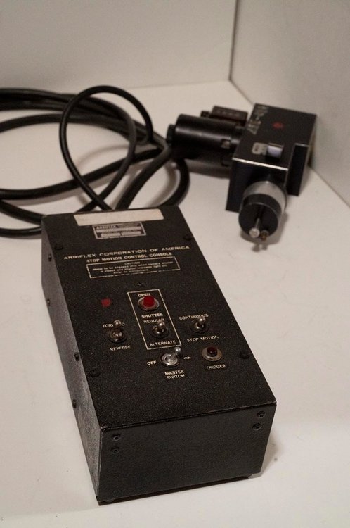
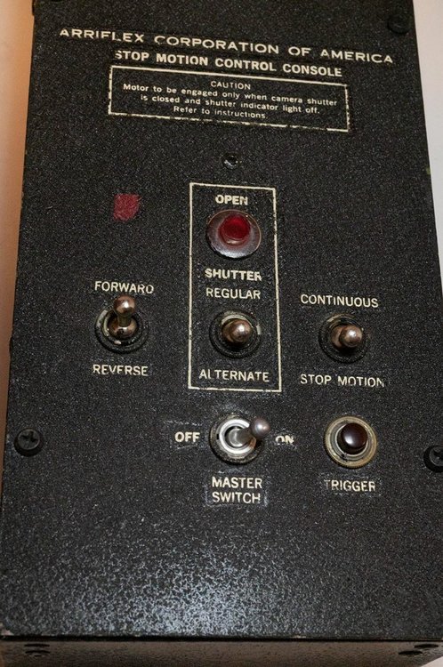
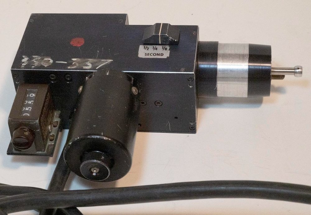
Oh and yes it works fully - forward, backward, continuous, two kinds of single step, etc. Duncan
-
I've been collecting various piles of used Arri stop motion equipment and have ended up with a second complete controller/motor unit, so I'm selling it. It's listed on ebay (I won't bother with the link because that'll be stale when someone finds this thread later on) but you can find it there and buy it from me that way or we can conduct a transaction here. If you do go through ebay, please do the "make offer" of something lower than my asking price and tell me you saw it here and I'll cut you a deal. I'm asking $350 there, will listen to about any offer here from the "in crowd" ? Duncan


-
Canon S16mm T2.4 8-64mm zoom lens with PL mount
Duncan Brown replied to Ville Piippo's topic in Cine Marketplace
Prettttttyyyyyyy!! Duncan -
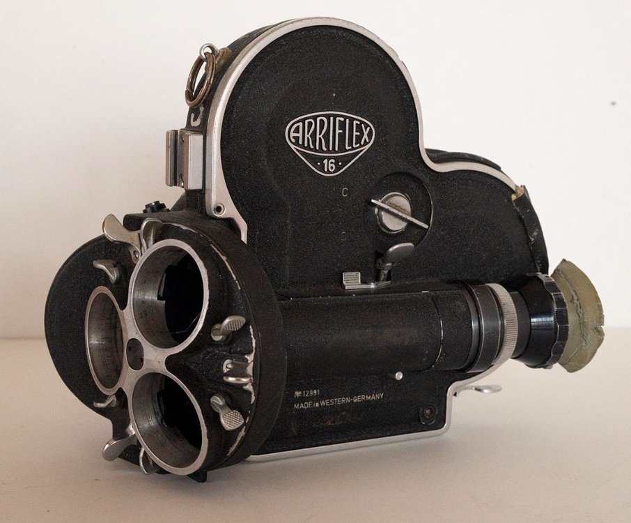
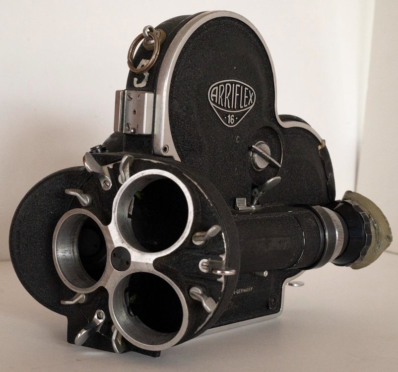
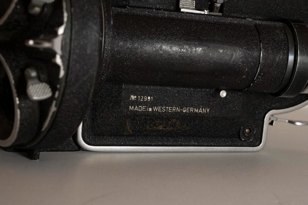
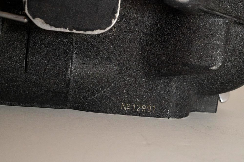
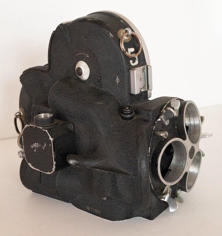
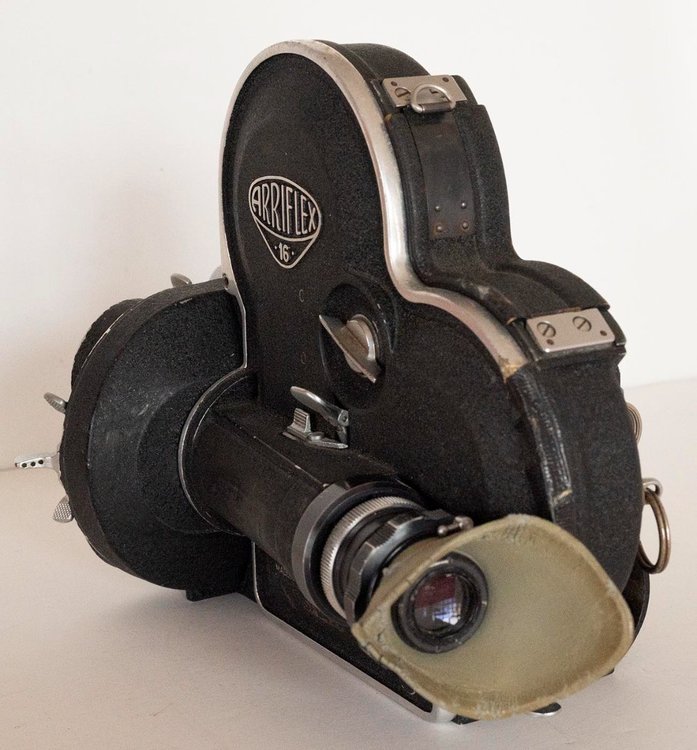
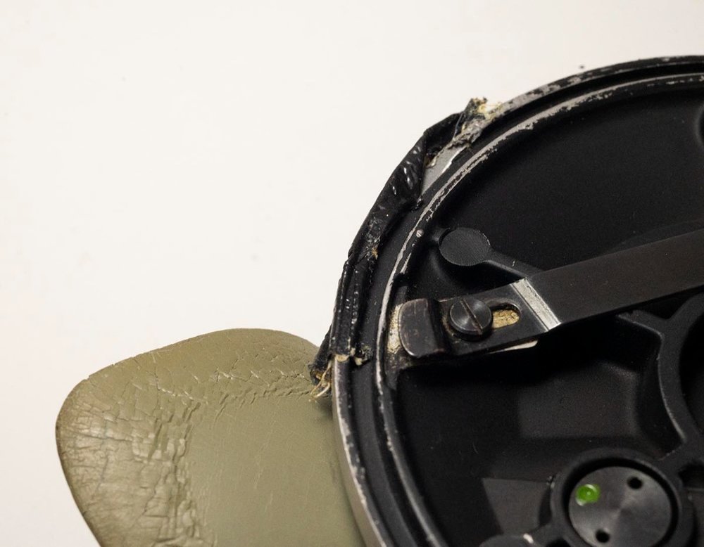
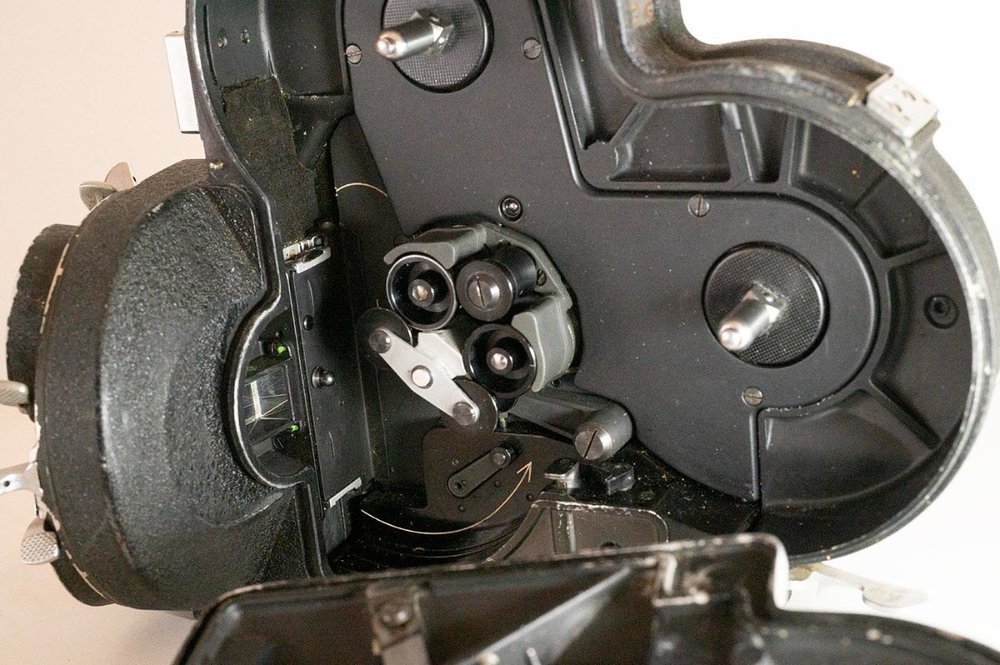
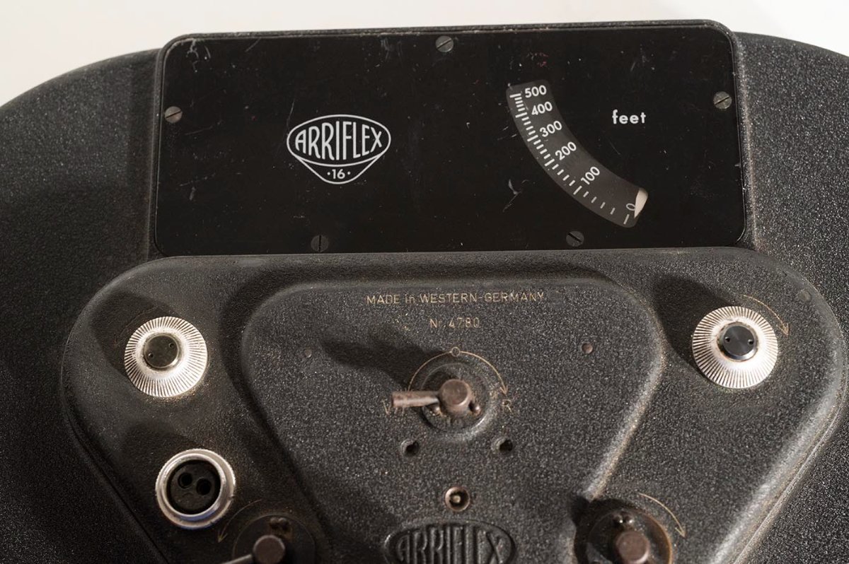
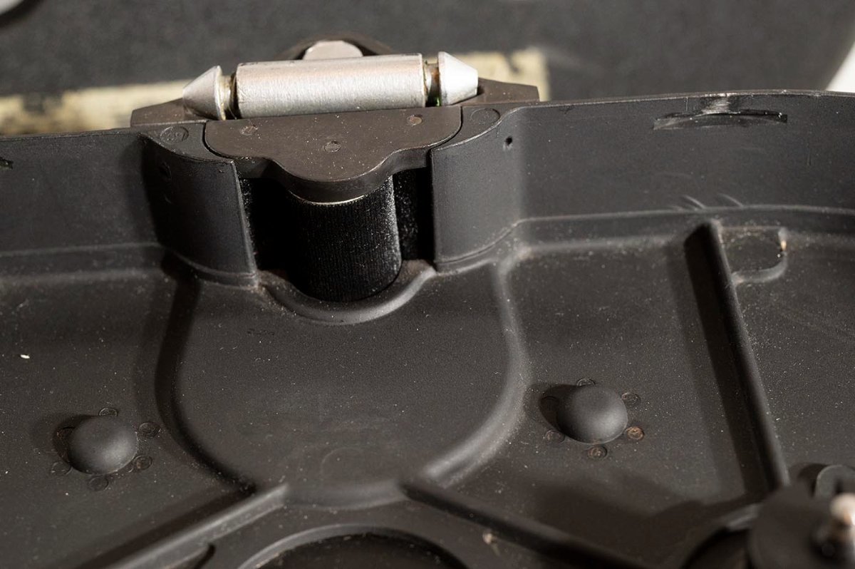
I've got too many projects, too many cameras, time to unload some stuff. This is a 16S that I bought as a parts camera but it's right on that line where it's probably worth putting back in service rather than parting out, and I picked up a couple of significantly worse cameras that I'm frankensteining into one so this one is just excess to my needs. The good: Everything is basically there, in pretty good shape and functional. It's got the magazine port cover, the cord latch that is sometimes broken off, a pretty good motor rubber coupling, pretty clean optics and mirror, etc. The bad: it's noisy when running, so definitely in need of a CLA. It was obviously just sitting on a shelf for too many decades. The turret spins and stops at the detents but is stiff. The tachometer doesn't move but that may also just be stuck from sitting too long. There's a little chunk missing on the outer rim of the door, which has been repaired with duct tape. The rubber eyecup is hilariously petrified. It looks like it's been repainted at some point. The missing: the dome and (is it a lamp?) from the Pilotone unit on the side. The dome from the bloop lamp thingy on the front top. The viewfinder cover flap (those are always gone, argh) Looking to get $400 but will consider offers the longer it goes unsold. Located near Chicago, but will ship anywhere that you'll pay for. Let's call it $15 Priority Mail in the US, actual costs elsewhere in the world. Duncan