


Friedemann Wachsmuth
-
Posts
145 -
Joined
-
Last visited
Everything posted by Friedemann Wachsmuth
-
A new development tank?
Friedemann Wachsmuth replied to Friedemann Wachsmuth's topic in Film Stocks & Processing
https://www.filmomat.eu/shop/manual-816mm-processing-system -
ORWO NC500 initial thoughts
Friedemann Wachsmuth replied to Tyler Purcell's topic in Film Stocks & Processing
I can't prove it but think you are on a wrong track here. ? Can't wait for your tests though! I'll shoot my two rolls next Sunday, haven't decided yet how I'll process them. I was considering ECN-2 and the getting a proper print, so that I can't really bend its curves. -
DIY - Reloadable Super-8 cartridges
Friedemann Wachsmuth replied to Thomas Larang's topic in Super-8
They always say that, even when I speak to other Germans ? Guess I should make an English version of that video, too. Too bad that currently no new Adox cartridges are being made, the tools are all still there though. -
Is there a demand for custom sync sound motors?
Friedemann Wachsmuth replied to Aapo Lettinen's topic in General Discussion
What does "ROV project" stand for? -
Is there a demand for custom sync sound motors?
Friedemann Wachsmuth replied to Aapo Lettinen's topic in General Discussion
Aapo, don't let yourself get down by this. My experience is That most people can't imagine a hypothetical product enough to get really hooked. Once you have a fully working solution, with all the kinks removed and bugs fixed, a manual, nice photos and maybe an example video, this will change. See how Kickstarter works. There is nothing but semi pro videos, mellow piano music and often pretty brilliant marketing claims. A scale of yummy pledges makes people not want to miss out. And at the end, some goon collected a lot of money, runs with it and never delivers. And you know what? Most "customers" forgot about their contribution and don't even miss their pledge. I guess that's just how capitalism works... ¯\_(ツ)_/¯ People seeing a prototype strip board with bodge wires on a messy workbench doesn't sell. It does gain interest, but not enough to make a commitment. My recommendation would be: Keep going. Don't think product. Think about what you want to achieve for yourself only. If you feel for that, share your thoughts and see what others reaction is. Feel free to ignore it. Harvest the gems that might have been brought up. Involve others only as much as you feel comfortable. Only then, when it works for you and you are 100% happy, consider making it a product. If you don't feel like productizing, you can still make it open source. That's my absolute favorite way to go. It is by far the most pleasing... for me, at least. -
Is there a demand for custom sync sound motors?
Friedemann Wachsmuth replied to Aapo Lettinen's topic in General Discussion
Huh, I feat I can't help you further w/o the actual schematics (if at all). I'd swap the cap as an almost free try (well, few cents, if you have none around) — that's low risk. BTW, when you have your Multimeter in Resistance mode, your are not "bridging" the cap. In the multimeter is a battery and you are sending a current through the test leads. That current might well also go thorugh the transistors (and whatever is connected with that cap) and hence "make it appear alive" — so I wouldn't bet too much that the cap is to blame. Germanium transistors do not like vibration/concussions. Might well be that one of them died. They are around 60 years old after all... -
Sorry, I had no intention to let you look bad! I apologise for how I articulated my post. At no times I wanted to be rude or let you look bad. I did not know that you intend to etch these boards on your own. I probably did not read that part. I do that with prototypes too, but usually not for production versions — dual layer edging DIY is hard, and JLCPCB takes $2 for 5 small 2-layer boards, so I usually go the china route. Just so you know, my last two JLCPCB orders (in COVID times) made it without problems to here (Germany, via DHL Express), while some Aliexpress orders are indeed still waiting. So I hear you on the board complexity ? I guess that's also why you are not considering SMT over THT to keep the size to a minimum?
-
Is there a demand for custom sync sound motors?
Friedemann Wachsmuth replied to Aapo Lettinen's topic in General Discussion
Wow, OC30 is one old germanium transistor! I am still not sure what you meant with "bridging". What Mode was your Multimeter set to when you measured, I guess on the two legs of that capacitor? I wouldn't be too sure that schematic you found is the same in your camera, but it is neither impossible. - If your cap is dead, like shortened, measuring over it in any mode should not make a difference. - If your cap is not dead, but lacks capacity (dried out), and your multimeter was in continuity mode, your brief "bridging" might have "simulated" what the cap was intended to do: Create a pulse (to get the motor going). Can you reproduce to start the dead motor with your "bridging" trick? And again, what is your multimeter set to? -
Is there a demand for custom sync sound motors?
Friedemann Wachsmuth replied to Aapo Lettinen's topic in General Discussion
Hard to say without seeing more of the schematics. It's a bit too big for a snubber. When you said "bypass", do you mean bridging it or taking it out? -
Sorry, Aapo, but if extra speeds mean extra costs, I think your approach is somehow fundamentally wrong. You didn't like my Timer-ISR suggestion for (almost) arbitrary reference clock speeds derived from one crystal. Your Atmega or Attiny has multiple of these timers built in already. If you don't like that approach, you could also take a Si5351 which generates up to eight frequencies of your choice between 2kHz and 200 MHz at once. Don't get me wrong, I just want to help you to keep the BOM low. Supporting more speeds should nowadays not bump the cost anymore.
-
Is there a demand for custom sync sound motors?
Friedemann Wachsmuth replied to Aapo Lettinen's topic in General Discussion
That's a 220nF / 300V cap. It is not supposed to let any DC through though, so probably not broken. -
Crossing fingers that you will succeed with this as a commercial project! I guess once you have your final PCB worked out and it all fits snugly into the camera, interest might go up.
-
Is there a demand for custom sync sound motors?
Friedemann Wachsmuth replied to Aapo Lettinen's topic in General Discussion
Oh I can relate. It helps though to clean up, which often allows simplifications, too. -
Nice work, Aapo! In the video it sounds as if your Leicina controller is overshooting when getting started, are you compensating for that later? I think phase-locking alone is not enough, you should also keep the impulse *count* in sync if you want synced sound. A quick hint for optical sensor: Lookup QRE1113GR. It costs pennys and does exactly what you need — two resistors and optionally lowpass/schmitttrigger and you got perfect TTL impulses with minimal space consumption. Allow me one more thought: Why are you dividing your pulses at all? Syncing up higher frequencies is much faster and allows "intraframe" controlling of the motor. Last but not least, the 8 bit PWM resolution of the Atmega isn't very much and might cause some jitter, no? I'd consider a broader PWM chip or a 12-bit I1C-DAC like the MCP4725 with a high impedance op-amp to drive the motor more accurately. That's what I did on my synced film viewer driver at least. Keep up the cool hacking and don't hope too much on customers. It is hard to swallow but actual buyers are almost non-existent. Do this for fun and make it Open Source, it's worth it!
-
Is there a demand for custom sync sound motors?
Friedemann Wachsmuth replied to Aapo Lettinen's topic in General Discussion
Aapo, have you considered using a PID-Controller? That's pretty much what they were invented for. There is even a great PID library for the ATMegas. Tuning the PID can be a bit fiddly, but no need to re-invent the wheel here, and a PID would work with any motor and basically any kind of motor, too. I love your Frankenstein-Breadboard-Setup though, looks exactly like the dozen of projects waiting on my desk for being finished ? -
Is there a demand for custom sync sound motors?
Friedemann Wachsmuth replied to Aapo Lettinen's topic in General Discussion
Aapo, it sometimes feels like you are over-complicating things a little ? Generating almost any custom frequency with crystal precision is about 10 lines of Code on any Arduino, no extra hardware needed for dividing. Just make sure your Arduino uses a crystal, not a resonator, many cheap clones use the latter, which is less precise. Also, I don't think there is a need for phase and frequency measurement. Just count and compare the pulses from both sources. The diff is the input for your motor driver. Done. -
Is there a demand for custom sync sound motors?
Friedemann Wachsmuth replied to Aapo Lettinen's topic in General Discussion
Why external counters? You should just use the Atmega/Attiny Timers. They are crystal acurate and give you almost any frequency directly without extra hardware. This gives you exactly 25 Hz on a 16 MHz 328p: // TIMER 1 for interrupt frequency 25 Hz: cli(); // stop interrupts TCCR1A = 0; // set entire TCCR1A register to 0 TCCR1B = 0; // same for TCCR1B TCNT1 = 0; // initialize counter value to 0 // set compare match register for 25 Hz increments OCR1A = 9999; // = 16000000 / (64 * 25) - 1 (must be <65536) // turn on CTC mode TCCR1B |= (1 << WGM12); // Set CS12, CS11 and CS10 bits for 64 prescaler TCCR1B |= (0 << CS12) | (1 << CS11) | (1 << CS10); // enable timer compare interrupt TIMSK1 |= (1 << OCIE1A); sei(); // allow interrupts ISR(TIMER1_COMPA_vect) { // Anything written here is called 25 times per second // once the above got executed } Here is a good primer, but there are many others too. Oh, and for 24 fps, you should create a 264 Hz timer and divide by 11 for the closest match. You get 264.000264000264... Hz with OCR1A = 60605 TCCR1B |= (1 << CS10); // Prescaler 1 which, divide by 11, gives you 24.000024.. Hz — that's more accurate than any crystal is. -
Is there a demand for custom sync sound motors?
Friedemann Wachsmuth replied to Aapo Lettinen's topic in General Discussion
No, I am not really interested in building a scanner. I am building an open source DC motor control for projectors, cameras, viewers etc, which costs a few $ only and needs barely anything else than impulses to run 100% locked at crystal speed. It doesn't care about altering friction or differing torques, it is always precise, not needing any adjustments — just control impulses from the motor or any other directly driven part. -
Is there a demand for custom sync sound motors?
Friedemann Wachsmuth replied to Aapo Lettinen's topic in General Discussion
Well, good luck then! ? -
Is there a demand for custom sync sound motors?
Friedemann Wachsmuth replied to Aapo Lettinen's topic in General Discussion
The current code and pcb design is at https://github.com/fwachsmuth/ErnoCCC — very dirty still and barely documented though. The way it basically works: A Timer ISR increments a counter as reference pulse. The shaft impulses (optical here) are wired to Interrupt pins too, using quadrature encoding — their ISR increments another counter. The loop compares the counters and uses the delta to impact the motor current — that's it. In my example, there is also a freq measure capability using ICP1 on PB0, this is only used when the motor gets manually controlled (to show how fast it is currently running). To derive the motor current, I use a DAC (12 bit) and feed its output into an R2R opamp, which generates the high impedance signal for the existing motor controller. There is also a calibration routine which iterates over voltages to find the current for two reference speeds, creating the math for any intermediate frequency needed. This is necessary since friction in all viewers differ, based on condition of the belts, bearings and lubrications etc. Hope this helps! -
Is there a demand for custom sync sound motors?
Friedemann Wachsmuth replied to Aapo Lettinen's topic in General Discussion
Here is an earlier prototype in action. The top line of the display shows the current frame count, the second row a SMPTE timecode. The button underneath cycles through 9, 16 2/3, 18, 24 and 25 fps — this affects the time code calculation on the one hand, the motor speed control on the other hand.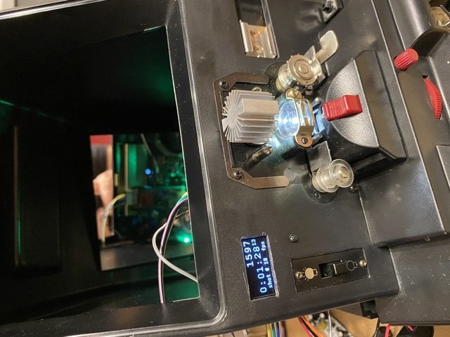
-
Is there a demand for custom sync sound motors?
Friedemann Wachsmuth replied to Aapo Lettinen's topic in General Discussion
Interesting Thread! Aapo, I am also working on a universal, crystal based DC motor controller. Mine is also 328p-based, but using impulses from the motor shaft to maintain speed. So independent from torque, speed is maintained with crystal accuracy. My current board is designed to be a replacement for Erno Motor viewers, but the concept is universal. I am also controlling Bauer and Braun Projectors already with this, using their organic impulses and "hooking up" to their existing controller, not replacing it. Contrilljj in mag any external camera motor would be trivial too, all I need is some impulses coming from the motor shaft or claw or so. I am also not afraid of PCB-CAD nor SMT-soldering. Also, you nowadays can order very small SMTA batches from China for little money. My code and w hematite are totally open source, so I'd be glad to join forces :) Here for example are the boards I just got on Friday, designed to fit into the motor viewer. Note the segment disc that gets mounted on the sprocket wheel shaft and never loses a single frame impulse. :)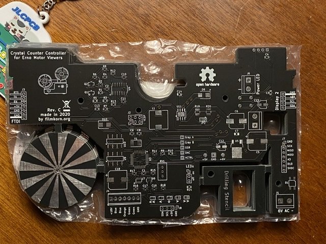
-
Bray E-Series Manual
Friedemann Wachsmuth replied to Friedemann Wachsmuth's topic in Film Stocks & Processing
Hey John, I am not sure about the config, the previous owner die C-41, E6 and bw-neg with it. He also offered me with help and answered my initial bunch of questions :) One Q: Is there any way to do the re-exposure for bw-reversal inside the Bray, not chemically but with light? My Bray has a kind of "gate" after the third tank, that suggests to allow a lightsource behind it, but I would not know where and how. I had been in contact with a Ruth Marsden at Bray Plastics, and just got a "I have asked the question and we have no manuals or paperwork in relation to the E-Series processors, we discontinued production approximately 10-14years ago and all relevant paperwork manuals etc. sorry we could not be of help." Weird. I still need to get tempered supply water and a drainer box installed at the place where I want the Bray to operate, so haven't even turned it on yet. Oh, one more Q: The previous owner used the 70mm leader and pulled up to four S8 films through it in parallel. Have you tried this too? Or even more films? -
Hey, I recently got hold of a Bray E-Series in working order. What a great little machine! I haven't fired it up yet, but it was in use until recently and is in really good shape, including spare parts. The only thing missing is the manual. Does anybody here have the manual and could scan it for me? I got the Manual of a Bray Magitrak, but it's not the same. I also contacted Bray Plastics in the UK (which is their name now), they claim to have no records, plans, schematics or anything about the E-Series anymore. Would appreciate any help! F
-
A new development tank?
Friedemann Wachsmuth replied to Friedemann Wachsmuth's topic in Film Stocks & Processing
Thats all good feedback. Keep the wishes and needs coming :)

