


Ryan Emanuel
-
Posts
88 -
Joined
-
Last visited
1 Follower

Recent Profile Visitors


-
Low contrast or Dark cinematography
Ryan Emanuel replied to Bineesh Viswam's topic in General Discussion
I think its important to understand what that noise is. The biggest goal in images is to have visually seamless gradients between pixels in representation of the scene. One of the variables the gradients are dependent on is bit depth. The bit depth per stops of DR of the capture device are not uniform, they are actually exponential and follow the formula 2 ^x where x is the stop of DR increment. So for the stop between 4 and 5 stops of light, there's 2^5 - 2^4 bits that will be allocated to the gradient between those light levels per channel. So as you can imagine, lower stops get less bits and higher stops get exponential more bits. Noise comes from inaccuracies due to not enough bit depth to make a visually seamless gradients. Since the camera is a machine and only can see discrete values, when it guestimates a value for a pixel each frame it can incorrectly measure the same value up or down a step simply cuz of rounding errors. When you have so many steps that a incorrect guess is still sooo close to the next step, visually you will never see it, but if there aren't that many steps than errors are visible as noise. So we want to increase bit depth in stops of DR that are allocated less steps in the gradient and more susceptible to noise. Many people never ask why we encode sensor data in a log container instead of gamma. We want to 'linearize' the relationship some what to make the bits per stop more uniform. When you have a function and want to undo the effect of the function you use the inverse. Log base 2 is the inverse of 2^x, it will restore the function back to y=x. Thats why we use a log function to reallocate the bit depth. When you have a 'linear' signal for the sensor data, that will not give you a linear bit depth response per stop. It will follow the 2^x allocation, The graph shows both how few bits are allocated to the first couple stops and how fast it explodes. You don need 200 bits+ bits to show the seamless gradation per stop, 30 steps of gradation are probably fine. So the log transform boost significantly the signal before encoding on the low end and suppresses it in the highlights. So variance is heavily reduced from linear sensor data. When you change ISO down and re-expose for the scene, like the green curve, it reallocates more bit depth to the low end, increasing the fineness of the gradient, which reduces noise. Other ways can accomplish the same thing like ETTR. Its all the same, but you just want to place the important the detail in the scene in a portion of the log curve that captures more information per step of DR, then the gradation was be visually seamless even after transforms down the road in post. SORRY MISLABELED THE LEGEND FOR THE GRAPH!! ORANGE = LINEAR BLUE = LOG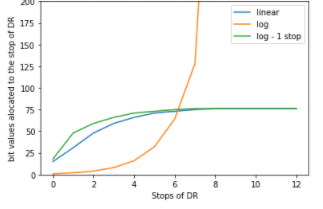
-
It's 2021 and digital capture still looks like sh
Ryan Emanuel replied to Karim D. Ghantous's topic in General Discussion
Luminance and gamut mapping is just normalization, take every value, divide by the max in the range and multiply by the max of the new range. Same with gamut mapping. You can do this with luts, Resolve just doesn't allow you to, to influence more dependency on the software, (my opinion). Thats why davinci isn't the best software to work with luts. It can only apply them really, you can't trouble shoot and qualify or normalize luts in Davinci. Also the Arri rec 709 lut is certainly different from a CST rec 709 gamma and color space conversion. Not necessarily better, just different looks made in completely different ways. -
It's 2021 and digital capture still looks like sh
Ryan Emanuel replied to Karim D. Ghantous's topic in General Discussion
I really hope not, they are not the same thing. CST is basically a 1,1,1 lut for 3D and a 10 lut for 1D, while 3D luts can be any resolution, you can have 128,128,128 with 2 million individual coordinates in the color space that can all be independently adjusted. 3d Luts are far more powerful. CST matches color space primaries, but just because pure red, green and blue are matched, ie three edges of the cube are matched doesn't mean the inside of the cube is matched. The true transform that maps one camera perfectly to another, is non-linear, so CST is ruled out cuz it can only do linear operations. The goal is to get your approximation transform as close to the true transform as possible. Thats literally the definition of a data scientist's job, this issue is statistics its not really color grading. Lets say you take some camera samples to a data scientist and the run a sequential neural networks to approximate every non-linearity in the color space transform. Their trained model will take pixel coordinate inputs from the first camera and output where that coordinate should be transformed to match the second, but you don't want to pass images through cuz millions samples would take forever to get processed. So you pass an identity lut through like a 33x33x33 with only around 30,000 samples. Also the neural networks can be normalized from 0-1 so no clipping. This is gonna be the future for color processing and how to solve that problem. We gotta just bring the right people to the table, a colorist won't be able to do this. -
It's 2021 and digital capture still looks like sh
Ryan Emanuel replied to Karim D. Ghantous's topic in General Discussion
The thing is, no lut should ever do that. -
It's 2021 and digital capture still looks like sh
Ryan Emanuel replied to Karim D. Ghantous's topic in General Discussion
Theres a few things going on here. First off any node based visual FX software works the same way. Each node is a math expression applied to the footage. In a two node system the first is nested inside the second. So whether or not the order of operations matters, is dependent on whether or not the order of operations matters for the math. If the first node is gain, then you are simply multiplying each pixel by a number. If the gain is set to 1.3 then if x stands for each pixel value, then the expression is 1.3 * x. The software stores that output in another variable like y and input that to the second node. Lets say thats a gamma correction, that math expression is square root of the image, or z^(0.5) ( z to the one half power is the same as the square root), z represents all the pixels values at the second node. Now lets input y for z, (1.3*x)^(.05). The question is if you do the operations backwards do you get the same thing? Not really you get this 1.3*(x^(0.5)). If you input the pixel value .6, you get .883 the first way after the color correction and 1 the opposite way. So for some operations the order matters its the same is you multiply in one node and apply a log curve in another 2 * log(x) is not the same as log(2*x). I strongly recommend messing around with desmos.com and plugging those two expressions in to see how vastly different the curves are. The second thing is encoding. Its important to know that images are just spreadsheets of numbers they can be anything. The caps that happen to those numbers are due to the monitor. It has a clipping function where any number past a threshold number gets saved as the threshold number, that is usually 1 when image values have been normalized between 0-1. BUT, that only happens when you encode, or save the numbers. If they haven't been saved then you can have pixel values at 99,000, when the monitor can only show 0-1, as long as you don't encode those values, the clipping function won't clip the actualy data the computer still knows the original values and you can bring those values back into range with an inverse function non destructively. What many people miss is that when you encoded or shot the footage with a log curve, There is already a math expression applied to the footage. So off the bat non of the color grading tools really work as advertised. Gain will effect the black point and lift will effect the clipping point of the footage. So in some image processing workflows you have to go back to linear as long as the manufacturer isn't hiding the expressing how to do that, so there is no math applied to the image before you work on it. Grading before or after the lut, is dependent on the operation you are trying to do and how complex the lut is. Like you don't want to do skin tone correction before the contrast curve and matrix adjustment. If the values are log they will be hard to key. That might be better after the lut, but scaling and offseting is probably not good before. -
It's 2021 and digital capture still looks like sh
Ryan Emanuel replied to Karim D. Ghantous's topic in General Discussion
This is one of those use the variable issues. Saturation from the HSL color space is the traditional variable people change for saturation on digital, but if you want digital to function like film, its the wrong variable for perceptible saturation. Film saturation is dependent on luminance and hue changes, so anybody adding HSL saturation to the shadows of digital won't get the right results. The tools in color grading applications aren't built for that. Its one of the biggest reasons why the common looks of digital are different than film, its the digital video engineers deciding the structure of how the color grading tools work. Its definitely not that its impossible to get it right, but in HSL its a square object trying to go through a circle. We'd all like to transform the square to a circle, but davinci won't do that, at least not easily. http://www.yedlin.net/NerdyFilmTechStuff/TwoKindsOfSatuartion.html -
It's 2021 and digital capture still looks like sh
Ryan Emanuel replied to Karim D. Ghantous's topic in General Discussion
This is what a lut actually is, sorry for the low res. Its a vector field, each arrow represents the transform for a coordinate in the color space volume. The lut is the arri rec709 33x lut subsampled down by a factor of 50 so you can actually see the different vectors. It would be hard to imagine that a colorist could capture all those vectors directions with color grading tools even subsampled for the entire space. I just don't know why there really isn't post software that helps you visualize the luts to see where the color is "flowing" in different segmentations of the lut. Visualizations like this(in higher rez and rotatable of course) would make the VF transforms more intuitive. You can also see from the perspective of the still that some of the trends of how the vectors are changing through the space are curves they are not straight lines, so linear operations won't capture the complexity..png.599a5c88f42014e8540cc064ecaf5816.png)
-
It's 2021 and digital capture still looks like sh
Ryan Emanuel replied to Karim D. Ghantous's topic in General Discussion
I would say there's literally zero places whether online or in film schools(other than AFI) that teach filmmakers what a look up table actually is. A lut stores 6 columns of tens or hundreds of thousands of coordinate data in a 2d list (hence the taxes). There are three inputs columns hidden in the indices, and three outputs that are the 2d list. 3 ins and 3 outs is basically a vector field. So any algorithms that apply to vector fields can be used for LUTs and color spaces. Most of the tools in davinci are linear operations, color matches are non linear functions. Usually color match color chart tools in software are projection or sum of least squares linear regression algorithms, they are still linear. Linear will always have significant error since the true function for the color space transform is non linear. If we want to solve some of these problems, we have to choose the right variables to work with. Like the halation thing. Highlight roll off and halation are not the same variable. Halation is the luminance artifacts that occurs at very high contrast edges, its not dependent on highlight roll off in the color space, so LUTs can't help you there. Edges are spatially dependent so then you need to convolve i.e. filter the effect spatially. You have to transform the image into the gradient domain where each pixel value changes to the difference in brightness between the pixel and the 8 surrounding neighbors. On high contrast edges that difference will be close to one, for all low contrast pixels will be close to zero. You have to run some tests to see how how large the halation is with respect to a point source and find a function that would approximate the shape and style of the halation. If the point source is has a 30 pixel diameter in the shot, is the halation diameter 60 pixel, 120 pixels, is it a circle or a star? Once you have that, activate the halation approximation at high values in the gradient domain. You can take this paragraph to a developer and they will make you a halation algorithm as long as you have the budget for the film samples. You gotta have the right variables that the problem depends on though. If you tell the developer the halation is from the lens, any algorithm they write is gonna be wrong. If a DP doesn't want to dive into these rabbit holes thats all good, literally zero careers are dependent on this stuff, but if we want to our craft to progress in the correct way, we have to be careful with what variables we say an effect is dependent on. -
It's 2021 and digital capture still looks like sh
Ryan Emanuel replied to Karim D. Ghantous's topic in General Discussion
His old algorithms are on github. Davinci in its newest iteration copied some of the idea. -
It's 2021 and digital capture still looks like sh
Ryan Emanuel replied to Karim D. Ghantous's topic in General Discussion
It depends, if you can't do your taxes in the software, its not the ideal place to make a look up table. -
It's 2021 and digital capture still looks like sh
Ryan Emanuel replied to Karim D. Ghantous's topic in General Discussion
I guess my question is why are people saying it can't be done, wouldn't it benefit everybody if it could. Like I was saying we should bring the problem to the people who can solve it. If you want unique spatial fidelity responses at different levels of detail for different texture patterns, that question sounds like a convolutional neural network problem, a deep learning data scientist can probably solve it. The hard part is matching pixel response for sample images, if you could match the pixels even for a small region of the chip on the two formats, a well constructed CNN would do the rest. People are gonna try stuff like that, my hope is that there are cinematographers there. Personally I don't know if color goes unnoticed, I think thats a pretty big component and still pretty difficult to transform really. You either need to automate thousands of color sample colors on both formats that span the entirety of the space and interpolate, or you work with a sparse data set and extrapolate anything outside the sample hull. That part is tricky, its one thing to linearly interpolate when you have sample targets near every possible point, but when you don't the chances of a linear extrapolation getting close to true values is pretty low. So you need some non linear extrapolation algorithm that matches the generalized trend of how each color changes on their hue/saturation vector. Thats a pretty iterative process, you get a lot wrong before you get anything right. -
It's 2021 and digital capture still looks like sh
Ryan Emanuel replied to Karim D. Ghantous's topic in General Discussion
A lot of issues get conflated, there is color reproduction, noise structure, halation artifacts, and a few other pertinent classifications for a look match. They all need to be discussed separately since the challenges are very different, when they get muddied together, its hard to make sense out of anything. It sounds like what you are talking about is noise structure and not color reproduction. Having one noise structure and layering another on top won't make a match. You need to take one noise structure and transform it to approximate another. Noise is basically errors. The distribution function that maps the variance of the errors can be transformed just like color spaces. Denoising is mapping the variance close to zero, but it can also be mapped to another distribution. If you add grain in software its probably just adding normally distributed noise, but film might not have a normal distribution structure for errors, it might have a different shaped distribution function. So you need someone who understands statistics, distribution functions, and signal processing to make the match. Again a colorist can't do that, and you don't know how film convert approximated the distribution, they could be right, they could be wrong. If you want to know its right, a data scientist or developer for signal processing can help. The democratization of all looks is coming whether we like it or not. Any look will be available on any camera that captures enough accurate data, once the right technicians are brought into the convo. -
It's 2021 and digital capture still looks like sh
Ryan Emanuel replied to Karim D. Ghantous's topic in General Discussion
Some art forms embrace technology others don't. It's tricky cuz aesthetically we plateaued decades ago as far as the most aesthetically pleasing color spaces for cinema. Most people would agree that film stocks have those color spaces, so many just shoot on film, it is the path of least resistance to the look. Nontheless, technology is allowing further and further transformation of color spaces, but DP's in general are not spearheading that endeavor. The issue for the future is the DP's primary collaborator for color is the colorist, who is an artist as well. They aren't an image processing technician, so for the problem at hand, a developer is needed as a collaborator. When you say digital can't match film, you are really saying there does not exist a function that can transform digital camera RGB color space, into film color space, it can't even be approximated. You are saying that there is nothing in computational geometry, supervised machine learning, or vector field interpolation that can solve the problem. That's probably not true, harder problems have been solved or approximated. A data scientist would probably say this problem is a piece of cake, DP's just need to talk to the right people. -
Adding breakers to sub panels in home locations
Ryan Emanuel replied to Ryan Emanuel's topic in Lighting for Film & Video
1. yes that was the original question. 2. 20A double pole, 30A breaker 3. Just one neutral for the coffee maker, it said in the manual that it only uses the 120v power for the clock, for the HMI both on the neutral. 4. You have to put the ground and neutral together, cuz the hmi will send more back on the neutral. 5. No, and don't know. 6. No it wasn't, for the light you would need a gfci 7. Its single phase so we were getting 245v from the two lines, if it was three phases we would get 208v, and that would raise the amp draw of the ballasts and potentially impact the correct breaker and wire. 8.Yes if the power factor correction is not 1, the ballast will pull more amps, potential higher than the threshold for the wire or connections. -
Adding breakers to sub panels in home locations
Ryan Emanuel replied to Ryan Emanuel's topic in Lighting for Film & Video
L14-30 is what I was talking about for changing the receptacle.

