Robert Hart
-
Posts
399 -
Joined
-
Last visited
Everything posted by Robert Hart
-
Properly Exposing on 16mm Film Question
Robert Hart replied to Max Thomas Schmitz's topic in General Discussion
The 1/3rd stop light loss may or may not be applicable. It will depend if you are using an original lens set supplied with the camera which has been calibrated to the camera for the numbers on the iris ring to appear "as if" there is no light loss. Lenses from other sources will be that 1/3rd stop underexposed. Better and smarter folk than I may explain this more accurately and and fewer words. -
intermittent overexpose of frames on 16mm footage
Robert Hart replied to Habib Beh's topic in General Discussion
There will be inside the gizzards of the camera, a centrifugal governor of some sort. For sake of smallness, the governor in a Bolex H16 clockwork camera appears to be controlled by friction of small leather boots inside a polished brass bell. The frame rate adjustment sets what rotational speed the friction pads engage the inside of the brass bell. Other industrial or internal combustion engine governors use spring resistance against the centrifugal force and some sort of mechanical linkage to a power controller, usually a throttle lever. What is inside the Bell and Howell I do not know but it will be a centrifugal governor of some kind. If there is any contamination of the friction surfaces in a Bolex, it must be cleaned. Otherwise there will be slight flicking as the governor hunts for correct speed across a wider variation than it should. If there are varying amounts of friction in the whole drive train, this will force the governor to hunt heavily for correct speed. It likely will not overspeed and underexpose, but at tight spots in the drivetrain, speed will drop back and cause your over-exposed frames before the governor can step back to restore speed. It is likely a service is needed which includes cleaning old dried lube off gears and thrust faces, relube and cleaning the governor, which should restore your camera. In the Bolex, a well maintained governor, set against a strobe source whilst the film transport is loaded will hold the camera in sync with a modern sound recorder for about 15 seconds, sometimes more. The Bell and Howell speed control may not be as accurate but there certainly should not be any light frames in each run except at starts and stops. You also need to be decisive when you button on and off. If you relax the trigger slightly, it may drag on the transport and cause your light frames. You also should not allow the spring to entirely run down before you button off. The high speed part of the mechanism may continue to run on under its own inertia and pull the spring end out of its retention. As mentioned above, given the price of the camera, you need to decide the cost benefit of having it fixed. Any other cameras out there which are offered for sale, unless they have been recently serviced, will likely have some speed issues, so my personal preference would be to suck it up and have it serviced. Mechanical devices with plain bearings, gears and springs, do need regular maintenance whether they are being used daily or sleeping on a shelf for six months.Your camera may well have been in hibernation for years. I was not able to hear sound with your video recording. A sound track with the vision might be more helpful. Please heed better advice from other folk. -
Help please on Lens Adapter
Robert Hart replied to charles pappas's topic in Lenses & Lens Accessories
Is it Cameflex to Aaton? -
Shooting old monitor (getting rid of moire/ aliasing)
Robert Hart replied to Bradley Roberts's topic in General Discussion
If you want to go with live display, you could try to defocus the LCD screen by cutting a piece of lighting tracing-paper diffuser to screen size and oiling it with barbecue spray or spraying hair spray on the textured face of the tracing paper to make it more transparent. You may of course still get screen-refresh artifacts. There may be other ways of doing this which are healthier for the LCD display you are putting it on, - oily side not touching the screen of course. You will likely need to use a spray. Wiping or brushing will leave bands and streaks. My personal preference would be to put a paper chromakey green mask on the display and adding the screen vision in post. With older curved CRT displays, it becomes a bit trickier to get a good lay up of a paper mask. I have had adequate but not best results using spray-on contact adhesive on a CRT screen then laying up a piece of carefully precut green pooltable felt cloth which has been lightly pre-sprayed with the same contact adhesive. You need to let the adhesive dry to be as tack-free as possible because you need to interpose a large piece of paper between the cloth and the CRT screen and carefully ease it out as you firm the cloth down to the CRT screen's curved glass surface. You most likely will still have to trim the edges. With care you should be able to "walk" any wrinkles out and not have to lift the cloth. Lifting the cloth will stretch it uncontrollably and you may have to start over. Please take the advice of others with more valid comments to make than mine -
You could probably get away with a non-toothed belt or suitably sized neoprene seal ring in place of the toothed belt but the footage counter would no longer register accurately and have varying and significant errors. Depending on how tightly the take-up clutch is adjusted or how much slippage the external o-ring magazine drive belt yields, there would be slippage on the internal belt which very likely would vary as the magazine drive loaded up with more film on the take-up core. A bricked or broken camera is highly likely to have a belt with missing teeth.
-
Inside the CP16s there is a memory battery. When this deteriorates, it may ooze onto a crystal module directly attached to the motor control board. It is quite a mission to get at it. You might strike lucky if the crystal module is covered with dried ooze and is successfully cleaned off but more likely it will have been damaged. Ken Hale at Whitehouse Audiovisual may have the necessary replacement PCB but I have not been in touch now for several years. There was a new digital replacement motor control system and rear control panel developed and sold. I don't know if the designer/builder/vendor is still trading or has any remaining inventory to sell. More details can be found at this page :- http://www.cinematography.com/index.php?showtopic=43586
-
How to degrade an image in-camera to simulate Old Spyglass
Robert Hart replied to Joe Taylor's topic in General Discussion
The magnifying glass suggestion is probably as good as any to try. You will be of course to use ND filters and shutter speed to control the light because as a camera lens, its aperture is wide-open. Once you have established the point forward of your camera's lens mount where sharp focus occurs from the magnifying glass to your camera's sensor, you may be able to control light with a simple round aperture hole tidily cut in a thin piece of card positioned between the magnifying glass and the camera. you will need a lightproof enclosure around the magnifying glass and the path between it and the camera. -
How to degrade an image in-camera to simulate Old Spyglass
Robert Hart replied to Joe Taylor's topic in General Discussion
Here is a young man's reflective arrangement of a plate camera and DLSR. -
How to degrade an image in-camera to simulate Old Spyglass
Robert Hart replied to Joe Taylor's topic in General Discussion
This linked clip of rather poor HDV quality was shot using a Sony HVR-Z1E, a 4+ power close-up lens for relay and a home-made AGUS35 adaptor with the groundglass removed for aerial image and a Sigma-for-Nikon 50mm - 500mm zoom attached on the front. The aerial image typically has a lower contrast and more often than not picks up the edges of the iris in this arrangement. It was with the available tech of those times, the only affordable long reach option for me at the time. Here is a link to a home-build AGUS35 groundglass device being dismantled to give you a sense of the principle. In this instance it is an image-erecting or "image-flip" arrangement with a prism pair. For your purposes that would not be a complication you need to have to deal with. Here is a large format arrangement which uses a plate camera, a Nikon DSLR, a macro lens which eliminates the need for a dioptre and a groundglass. This arrangement is unlikely to work in aerial image mode due to the wide angles of view of the optics and the projected image but who knows? In this instance, the builder has used a fresnel "condenser" lens in the path between the front lens and the groundglass to eliminate the vignette defect you may will be looking for. The "Coatwolf" camera used for the independent film "Bellflower" was a similar arrangement except the used was one of the early SI2K camera heads. -
How to degrade an image in-camera to simulate Old Spyglass
Robert Hart replied to Joe Taylor's topic in General Discussion
You could try using an old zoom lens, decollimate it drastically relative to the mount by removing or adding shims which are often found between the mounting tail of the lens and lens body. Finding focus will be interactive with the zoom movement and you may find the edge of the image goes off focus or weirds out in some way. Make sure you do not lose any shims so that you can restore the lens later. As mentioned above, optics in the olden times were not perfect. Until a very recent theft, I had an old pair of binoculars dating from about 1910 of a non-prismatic design which yielded a clean image to the eye. Old optics are often degraded due to age and no longer representative of their original image quality. You might otherwise try a leaf out of the old 35mm groundglass adaptor book and shoot the aerial image from another lens in front of your camera's own lens. To achieve chroma abberation, edge softness and even coma ikn the edge as a bonus, you would use the cheapest single element screw-on close-up lens you can find and stack the for 7+. You could get away with 4+ but your forward offset which I mention further along this response would need then to be about 7 or more inches ( approx 800mm ). The method is awkward and unwieldy. You would attach a 7+ close-up dioptre lens to the front of a camera lens of about 100mm focal length for a small sensored DLSR, the smaller the front element of that camera's own lens, the better. Then position the tail of another lens about 6" or 150mm in front of it and aquire the aerial image of that lens in front which will need to have a large exit pupil, think 20mm wider or more. You will need to make a lightproof enclosure or your image will be contaminated by ambient light. To set up, your aerial image plane, you will use a small paper target with some marks on it. Move this forward of your camera with its lens and close-up dioptre until you have a clear image. The position the flange face of your other lens in front a further 44mm forward if it is Canon, 46.5mm further forward if it is Nikon or 52.0mm furthur forward if it is PL-Mount. When you remove your paper target you will be in the ballpark of aquiring an aerial image through the lens in front. That image will appear upside-down. Depending upon the size of the exit pupil of that lens you will get a vignette which may or may not be manageable. Ff you have the front lens focused for close-up and moved slightly rearwards to restore sharp focus on a distant object, then there will be a definite edge defect in the image and likely a vignette from the iris as well if you close it. Whilst I have some regrets at dismantling old equipment, an old groundglass relay adaptor like a Letus35 Extreme or Ultra can be used in aerial image mode with the groundglass removed. You need however to use the camera type for which it was built which usually means 1/3" sensored cameras and a focal length setting on that camera's own lens of about 60-70mm. The relay lens and mounting ring on the back of the Letus is also specific to camera type. With an erecting groundglass adaptor like Quyen and Hien Le's Letus, Dennis Wood's Brevis and Wayne Kinney's later SG Blade designs, the groundlgass panel is relatively simple to remove after the adaptor's front case is opened up. A P+S Technik Pro35 is suited to 2/3" sensored cameras but removing the groundglass is a real mission and likely to be destructive. There have been a few experiments with large format plate cameras by either filming the screen image of a large 6" groundglass plate or bouncing the large format lens image with a mirror forward onto a reflective screen within a lightproof box and photographing that reflected image. You would find this very bulky and awkward. My personal preference might be to use post effects as suggested in previous responses above. -
Angenieux 16-44mm zoom ( Variable prime ) T1.1.
Robert Hart replied to Robert Hart's topic in Lenses & Lens Accessories
Dom. Thank you for your response. I have some machining skills and small lathe and have previously made PL and IMS mounts and adaptors for Speedboosters. PL-Mounts are tricky but doable if you are precise and get the method right. The mount arrangement in this lens appears to be as you say, an intermediate piece with the mounts in my two specimens permanently fixed to it by press or thermal shrinkage. I may go the route of a third-party ARRI B/Standard to PL-Mount adaptor and turn out the inner diameter to suit or remachine the Cameflex or Aaton tail with a suitable thick shim to move the flange face forward. The entire intermediate piece is a bigger ask of a home machinist in that the thread pitches are very fine. One version of a PL-Mount I have seen on reduser appears to have been an intermediate adaptor and PL-Mount tails for Optar Illumina lenses. If I can get hold of the machining detail for that intermediate adaptor I would have a shot at making it. Collimation I can handle - with due care of course. -
As a long shot I enquire if anyone has a machinist's diagram or design for a PL-Mount for one of these fairly rare lenses. I am building up one out of two which have different defects. One has a cameflex mount, the other which is very incomplete but fortunately has a good front element has an Aaton mount. Given the move to 4K+ these days,a 2/3" / Super16mm digital cinema camera image is a harder sell but then again am not quite so hard to please and happy to use an SI2K with Optar prime lenses. Any advice appreciated. An online enquiry with Angenieux yielded no reply.
-
Somebody like Les Bosher in the UK would be able to do it and do it better than I by a huge degree of quality. You would have to buy a Metabones Speedbooster with 0.71x "Ultra" optical cell in it and remove this from the Speedbooster. Nothing destructive has to be done to the optical cell itself so you would be able to re-assemble and resell it if you want. The optical cell is identical across all the "Ultra" 0.71x speedboosters. Used off eBay may be the most affordable way to get one. Metabones or Caldwell Optics will not sell you the optical cells singly. I can provide the construction method and some dimensions. Les Bosher would probably prefer to measure the work to be done himself. https://www.ebay.com/sch/i.html?_from=R40&_trksid=m570.l1313&_nkw=Metabones+Speedbooster+ultra&_sacat=625
-
If the lens is silver you may find it was made by Tamron. Years ago, I used a version of the Sony/Tamron lens from an old 1/2" reel to reel EIAJ camera and recorder system on a Bolex H16, then later on a Bolex H16RX5 for stringer news work. It was adequate but not outstanding for sharpness. This vision was shot with the lens. Unfortunately the transfer from film to digital vision is very poor but it may give you a hint if you compare the sharpness of the image with the blemishs and scratches on the film itself.
-
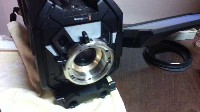
Here is an image of the Nikon F-Mount arrangement with the speedbooster installed. The front face of the mount is rearwards within the body of the turret. You will observe extra unused screwholes in the bronze mount adaptor. I have not yet devised a lock pin arrangement which will fit within the available workspace of the PL-Mount camera body
-
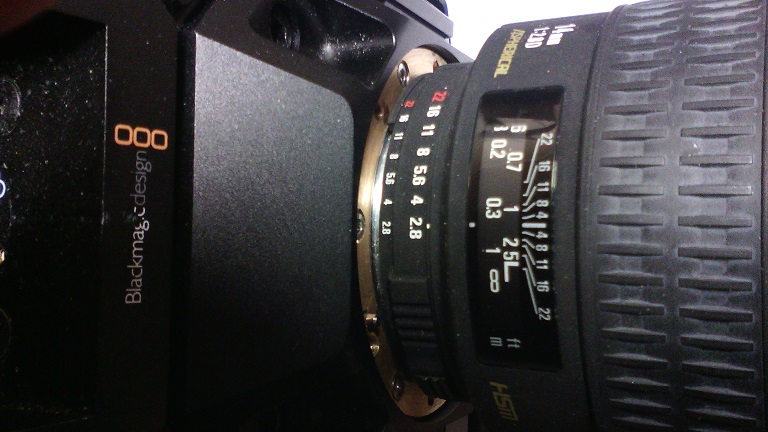
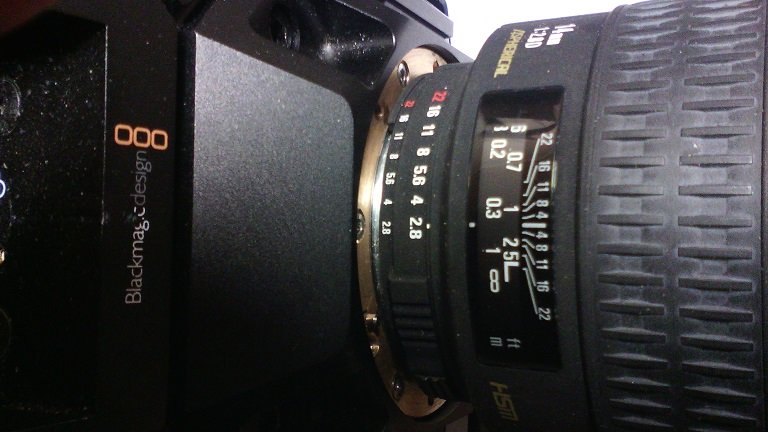
Here are some images of the PL-Mount with Speedbooster installed. You will observe that the rear of the clamp ring now approaches extremely closely to the front of the turret body when the lens is secured.
-
I could not get the link to work as a windowed view in the responsive post second above this post, so here it is again, windowed this time.
-
Further to the above, an enterprising fellow in Italy has devised a focal reducer to fit within the camera throat of the URSA Mini 4K and URSA Mini 4.6K cameras. It is called the Lucadapter. Unlike my arrangement, it apparently does not require the 4.2mm setback of the lens mount flange faces of the Nikon F-Mount and PL-Mount that my arrangement of the Metabones 0.71x optical cell requires for infinity focus to be preserved. Because the URSA Mini Pro camera throat is occupied by the ND filter system, it is not suited for fitment of a focal reducer like the Lucadapter or custom adaptor for the Metabones 0.71x optical cell.
-
My apologies for not posting follow-ups. I found myself locked out until I discovered that the password only works at the home page of the forum for logging in, the same as happens on the BM and bmcuser forums. Other sites behave differently, a mystery beyond my meagre comprehension. - Anyway back on to task. I managed to devise a useful solution for the Nikon F-Mount which I made for the "Big" URSA PL model by machining the "tail" of my Nikon adaptor piece to hold it forward from the rear face of the wide recess in the camera body which normally accommodates a cylindrical adaptor piece. The Nikon adaptor must have two sets of mounting holes to match the distinctly separate patterns of the camera body itself and the adaptor ring which has its own screw holes in it. I also discovered that the BM URSA PL-Mount can be adapted to work with the speedbooster in place by machining a little off the tail of the mount so that like my Nikon adaptor, it butts against the rear surface in the camera bodywork. A small amount of material must be machined off the rear of the clamp ring and the two finger lugs to clear the front face of the camera body. I should but have not yet made a spacer piece to surround the shortened tails of my mounts. Unless the mount screws are pulled up carefully and equally to correct tension, it is possible to tilt the mounts which is not good. The only lenses which are safe to use with the Metabones 0.71 optical call in place are the lenses Metabones has tested and approved. These are as far as I know, the Zeiss CP2 series of compact primes. Rokinon Cine/Samyang Cine and Xeen PL-Mount lenses should work as they are fullframe SLR based designs which do not penetrate deep inside of the PL-Mount. Most traditional motion picture camera lenses may clash against the front element of the Metabones 0.71x optical cell, damaging the cell and the rear element of the lens. Old Cooke Speed Panchro Series 1, 2 and 3 are definitely not suitable. Please ignore the colour in this accompanying vision. I am partially colour-blind and cannot colour-grade to save my life. On the "big" URSA, with the 0.71x in place, the 28mm Nikon lens used became usefully wide-angle in the confined workspace of the cottage kitchen. The 58mm Nikon lens field -of-view was usefully wider. https://www.youtube.com/watch?v=8jh0p7ljhYc&t=94s
-
With some, not all lenses, wrap several turns of some cotton thread into the narrow gaps between aperture/zoom/focus rings and lens barrel and tie it so loose ends do not migrate under and jam the mechanisms. This does not stop fine drift sand from getting in but helps prevent it from migrating underneath. This does not work with focus barrels which move along the lens body as you move focus. When you pick the cotton thread out, some of the fine drift sand will come out with it. it is best to sleeve or bag the lenses and the camera body as much as you can without making the whole thing too hard to operate or risk overheating the camera.
-
Matias. Please obey the advice of people more skilful. My personal preference would be :- Shoot some tests without filters in normal lighting environments. Any filters will remove light and in the night you need your camera the best it can be. Set your camera shutter slow so there is motion blur. In your colour grading software, desaturate all colours. Lay a green tint over your black and white image. Don't just pull up the green channel of your original footage. Ramp up the contrast so that highlights like lamps or highly lit parts of the image burn out. If there is gain noise from the camera sensor, so much the better. Don't try to clean up the sensor noise. If you wan't to replicate the trailing smear of strong highlights of some older NV devices, copy the footage to a second and third video track with each one frame delayed. So second track is one frame delayed, third track is two frames delayed. Transparency of the two overlaid tracks should be approximately 30%. Stacking delayed vision layers like this will reduce the intensity of the sparkle artifact or gain noise of the sensor to an artifact which will look more like low contrast film grain. You may need to pull the contrast of the master track up even more until you have the look you want. Good luck with it.
-
I forgot to mention, what the human eye sees via a night vision intensifier is of apparent better crispness than what a camera sees. The scintillation artefact ( video noise of an intensifier ) seems more sparkly and bright than what the camera sees. Using an intensifier to a camera may depending upon the type and camera adaptor provided, may require two focusing operations, one for the taking lens, the other for the camera's own lens which has become a relay lens. Managing two focus operations can be a real pain and consume time. The gold standard for mounting intensifiers to cameras I understand is the Astroscope family of kits by Electrophysics Corp. Their best kits can only be accessed and used within the US as there are export restrictions on certain grades of intensifier tubes for national security reasons. The company builds kits for the widest range of cameras and may by now have a kit for Sony E-Mount as well as the more well known camera types. Here is a link to information about one kit which may be suitable for the Sony F55 if there is a Canon EF-Mount ( EOS-Mount ) available for it. My personal preference remains with shooting a clean image and adding the artifacts and softening the image if need be in post. www.militaryandlaw.com.au/shop/item/9350-digital-35mm-still-cameras You need to scroll to the bottom of the page and download the .pdf file from a link provided. You may need to experiment with best time of day to shoot your night vision effects shots. With modern intensifiers, the sky can be seen. So you might need to shoot day-for-night because at night, your camera at its highest gain, may not see the sky unless you are in an environment where there is strong light spill into the sky from a nearby city.
-
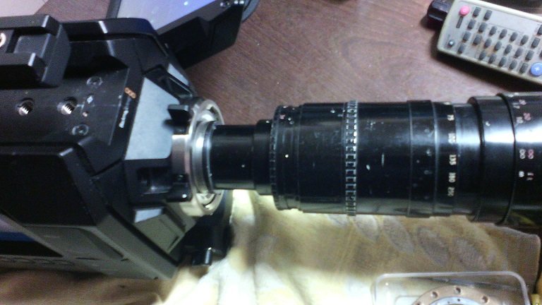
If you intend to shoot the display screen of a night-vision tube intensifier, there are difficulties unless you have a specific kit to mount that device onto a camera. I understand, maybe wrongly that the display resolution of a 2/3" intensifier in the Gen 3 or Gen 4 class is still only about 72 line pairs per mm at best. That is around about the sharpness of standard definition television. By the time you frame out the circular display edge from your rectangular camera image, the resolution is reduced by about a third. For dramatic purposes, the circular image might be retained as a porthole in the rectangular camera image. I understand that for most motion picture dramas, a clean image is shot with a conventional camera, colour-desaturated, tinted green and the signature artifacts of the intensifier tube display added in post-production. Those artifacts are in case of over-bright image are hex outlines across the image replicating the stacked coherent fibre bundles of the image-inverting device within the intensifier tube or a sparking noise in the vision which in night-vision speak is defined as scintillation. Overbright areas within the intensified image are sometimes replicated by letting the originating camera image blow out the highlights. This image was shot a Gen 2 intensifier of 60 line pairs resolution. For much of the tine there was sufficient lighting for a modern high gain camera to aquire a usable image and I had to close the aperture on the taking lens to outdoors daylight levels tgo avoid blowing the tube image out. Because of adequate light levels, there is no gain noise or scintillation in the intensifier display. You will observe I chose a compromise between portholing the display image entirely or cropping out the circle altogether. In this image with the same Gen 2 intensifier, I was experimenting with a Metabones speedbooster for BMPCC in the optical path between the intensifier tube and the taking lens which brings the "apparent" image recovery up into the Gen 3 class. Of course a Gen 3 would perform even better with the same optical setup. You will observe that the sharpness in the image drops off in the much lower lighting conditions and the scintillation artifact challenges the camera's compression scheme. My personal preference would be to go with conventional camerawork and add the effects in post.
-
I was told that a few years back, a local director and DoP here in Western Australia shot a short film "Ronan's Escape" on 35mm and Super16mm, apparently on the same stock, apparently not by choice but driven by the 35mm camera breaking down and there being no replacement in time ( Affordability might have been a factor ). Director was A. J. Carter who has since moved to the US West Coast and DoP was David Lemay. Full movie. Trailer. The underscore for the trailer is a sweet piece of music. I don't know whether the full movie's credited composer Hamilton Cleverdon prepared the trailer underscore.
-
I am not sure if advising of an item for sale for a colleague is correct or not but here goes for now. In Western Australia, there is an Elemack Spider dolly with a Ronford Baker old-school fluid head attached to the 150mm bowl by an upstand on short columns, lengths of straight rail and a half-circle of curved track, studio wheels and pipe rail wheels, seating and low arm. Except for the low arm, all other parts are in industry transport boxes. It is offered by Steve Rice who now lives in Thailand. He wants $8,500 for it. He has it listed on the facebook. If you have a facebook account, you can find the listing here. https://www.facebook.com/groups/broadcastgearforsale/permalink/1662416403817500/?sale_post_id=1662416403817500 If you wish to contact him direct, his email is darlingfilms@hotmail.com