Premium Member Steven Jackson Posted January 15, 2021 Premium Member Posted January 15, 2021 The motors are fairly straightforward to disassemble but careful of the fine wires that run from the front to the rear, where the commutator and brushes are. They break off very easily. I would be interested to know more about changing the bearings and a connection to the supplier and reference number. I have a few disassembled motors if you need photos before taking yours apart.
James Jeffrey Cotter Posted January 15, 2021 Posted January 15, 2021 Do you have any photos of the part numbers on the bearings you need? I have a very large quantity of new old stock Arriflex bearings of all different sizes.
Premium Member Dom Jaeger Posted January 15, 2021 Premium Member Posted January 15, 2021 On 1/15/2021 at 5:54 AM, Duncan Brown said: why is there a matte black stripe dead center on each of the two mirror portions of the shutter? The stripes increase the flicker rate, which makes the image seem less ‘flickery’. Similar to how film projectors use triple bladed shutters to increase the flicker rate to more than the actual frame rate, a higher flicker rate creates an image that feels more constantly illuminated. Regarding the motor, if it is running at a perfectly constant speed then your problem is not a stiff camera movement or sticky bearings or a slipping rubber coupling, issues which as you surmised would create uneven speeds. It would seem that the governor itself is out of tolerance, an electronic issue possibly caused by ageing components. I’ve never adjusted one, and I’m not an electrical technician so I’m sorry I don’t know what’s involved. If you had access to a power supply you could see if raising the voltage increases the governed speed, in case it is a 12V motor (in my experience motors that look like that are 8V, but there may have been later 12V versions).
Premium Member Duncan Brown Posted January 15, 2021 Premium Member Posted January 15, 2021 Looks like there is a motor teardown/investigation in my near future! I'll be sure to take pictures. Duncan
Premium Member Michael Leake Posted January 15, 2021 Author Premium Member Posted January 15, 2021 https://www.mcmaster.com/bearings/ball-bearings/ above is a link where you can buy bearing. IF the bearing has numbers and letters stamped on them, finding equivalents will be easy. IF not , then you will have to carefully measure bearing outside diameter, shaft diameter and thickness.. They are most certainly metric.
Premium Member Duncan Brown Posted January 16, 2021 Premium Member Posted January 16, 2021 Interesting about the mirror stripes - that actually makes sense! Before tearing down the motor, I actually did a little more testing on the camera. With the battery hooked up and the switch on and the motor out, I can measure the voltage at the motor contact. It's the exact same as at the battery, so I'm probably not losing anything through the camera (yes, it's possible somewhere there's a high resistance that would affect the motor but not my meter, but again I would think that effect would not be so precise as I'm seeing.) BUT!! The voltage is 9.4V. My fully charged nominally-1.2-V cells are putting out more like 1.35. Could that affect the motor governing? I guess I could modify my pack to tap off of 6 cells instead of 7, which gives me like 8.1V fully charged, but it would drop to 7.2V after some use I would think. Hmmmmmm Duncan
Premium Member Duncan Brown Posted January 16, 2021 Premium Member Posted January 16, 2021 9 minutes ago, Duncan Brown said: BUT!! The voltage is 9.4V. My fully charged nominally-1.2-V cells are putting out more like 1.35. Could that affect the motor governing? I guess I could modify my pack to tap off of 6 cells instead of 7, which gives me like 8.1V fully charged, but it would drop to 7.2V after some use I would think. Hmmmmmm Answered my own question by just doing it - tapped the pack at 6 cells, gives around 8.1V unloaded, still runs at the exact same slow speed. Time for some motor surgery. Duncan
Premium Member Duncan Brown Posted January 16, 2021 Premium Member Posted January 16, 2021 OK, full pictures and details coming later, but I got the motor all apart and back together again, and adjusted to about as dead-on to 24fps as you can get with an electro-mechanical governor like that. (I can see why people eventually went to crystal synced motors) For the technological era involved, it really couldn't have been any simpler to adjust the speed, if that's all you need to do. And in the end that was all I needed to do. My bearings were fine, my main brushes were fine, one of the governor brushes is getting on down there but given the level of use I'll give it, will probably never get to "worn out." Even replacing the bearings would only require one wire to be desoldered, and one roll pin or something to be pressed out (where the drive ball is held to the shaft.) Kudos to Arri, this is a good design for the time. I do have a spare stock variable-speed motor coming, which I'll pull apart and document too, but guessing it's pretty similar. Duncan
Premium Member Steven Jackson Posted January 16, 2021 Premium Member Posted January 16, 2021 look forward to seeing the pics
Premium Member Duncan Brown Posted January 18, 2021 Premium Member Posted January 18, 2021 As promised. http://backglass.org/duncan/arri/constant_speed_motor_24fps_teardown/ When I get my spare variable speed motor I'll give it the same treatment. With luck it will use the same bearings, so I can go the extra mile and pull them off to parameterize them better. Still wondering about the seemingly spurious number on there. Duncan
Premium Member Dom Jaeger Posted January 18, 2021 Premium Member Posted January 18, 2021 Thanks Duncan, nice write-up.
Premium Member Steven Jackson Posted January 18, 2021 Premium Member Posted January 18, 2021 Great. Thanks for sharing this.
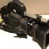
Premium Member Duncan Brown Posted January 18, 2021 Premium Member Posted January 18, 2021 (edited) Oh just another trick I learned along the way. I have a later camera, for which replacing the drive coupler "requires" pretty deep disassembly to be able to hold the transmission in your hands to replace the coupler. That seemed a bit much to ask just to replace a rubber tube, so I figured out a vastly easier way. Just work down through the motor opening! Now, you need to be especially careful not to drop little parts down into the bowels of the camera, so this is not for the faint of heart. But with the right tools, it just took me literally a couple of minutes. At which point I wasn't sure I had gotten the little pinch rings in properly so I took it apart again... discovered I HAD, indeed, done it correctly, then put it back together again. I bet Arri had a custom tool that did it this way, perhaps with some grippy and/or curved surface on the tips to minimize tool marks, but this definitely gets the job done. These two pictures should explain it all, let me know if they don't. (I'll put the second one in the next post, because it says the two of them are too big for one post.) Duncan Edited January 18, 2021 by Duncan Brown
Premium Member Steven Jackson Posted January 18, 2021 Premium Member Posted January 18, 2021 I figured this could be done! Glad to see it has been proven.
Premium Member Steven Jackson Posted January 18, 2021 Premium Member Posted January 18, 2021 That is so great. I had actually written to Sean Charlesworth about whether this was possible but was discouraged from doing it but it seemed like a feasible idea to me (of course, my attempt probably wouldn't have gone as smooth as yours!). My camera is a later model where full disassembly is the norm for this procedure. Excelllent. Thanks for sharing this.
Premium Member Duncan Brown Posted January 18, 2021 Premium Member Posted January 18, 2021 (edited) I bought Sean's kit to do the replacement. I'm pretty sure he's morally obligated to discourage you from doing it this way, as it's insane. He also won't help you do it that "right" way on newer cameras because that is also insane and should only be done by a real experienced competent Arri tech. As far as he's concerned, his kit is only for the older cameras with the two bolts holding the transmission. But, here you go. Next tech who disassembles this camera will probably curse the light tool marks I no doubt left on the transmission shaft, but frankly the nut simply wasn't that hard to spin off. the 11" handles allow a pretty tight grip at the tip of the pliers, and there was no slipping. So any tool marks would be insignificant. Duncan Edited January 18, 2021 by Duncan Brown 1
James Jeffrey Cotter Posted January 19, 2021 Posted January 19, 2021 (edited) Arri did not have a special tool for this, the entire piece is changed in an overhaul. I cringed reading this, but I am happy it worked out. Edited January 19, 2021 by James Jeffrey Cotter
Premium Member Duncan Brown Posted January 25, 2021 Premium Member Posted January 25, 2021 Took apart a standard variable speed motor and documented it, but I'll wait to post that until I have some new bearings and put it all back together again. It's more complicated than the constant speed motor, and you have to desolder two wires to get it completely apart. This is one I bought used cheap on ebay - and the variable speeds were all over the map as I spun the knob. I'll be interested to see if just cleaning it all up and getting the slidy contacts going on a slightly different path on the variable resistor windings manages to restore it to stable operation. The bearings are indeed the same spec as the constant speed ones - 5mm shaft hole, 16mm outside diameter, 5mm race width. That matches up with the GRW 625 number that's stamped on it, still not sure what the extra 634 number is about. The other motor had bearings that had metal dust shields on both sides. This one had a metal shield on one side, and open on the other, This motor had definitely been worked on before, as there was kind of nasty grease in the bearings, and someone had jacked up the pin that holds the ball drive on the shaft. The original looks to be maybe a brass drift pin, whereas this one had clearly been clamped in a vise before, and someone had tried to drive a roll pin in and broken it off halfway through and then put a nub of another roll pin in from the other side to hold things. I had to drill the whole mess out in a drill press, and will have to come up with some kind of brass drift pin to put it back together. On eBay I ordered some bearings out of Michigan - 10 for $7.99 - with rubber dust shields on both sides. Those have a generic part number of 625-2RS ("2 Rubber Shields"). I also ordered some from China, 10 for $3.99 with free shipping (!!!) that have steel shields on both sides, generic part number 625-ZZ. I'd prefer the steel shields like the originals but A) I'm impatient and B) I'm not sure I trust Chinese bearings that are 39 cents each shipped. But I figured I'll get both kinds and eventually be able to compare them. Stuff from China usually take a month or two to arrive. Duncan 1
Premium Member Simon Wyss Posted January 25, 2021 Premium Member Posted January 25, 2021 5 hours ago, Duncan Brown said: The bearings are indeed the same spec as the constant speed ones - 5mm shaft hole, 16mm outside diameter, 5mm race width. That matches up with the GRW 625 number that's stamped on it, still not sure what the extra 634 number is about. 634 means stainless. https://www.skf.com/group/products/rolling-bearings/ball-bearings/deep-groove-ball-bearings/productid-634
Premium Member Steven Jackson Posted January 25, 2021 Premium Member Posted January 25, 2021 Ducan, this is really valuable information and I am so glad you are taking the time to document what you are doing and sharing it. Once you have posted the photos etc for the variable speed motor, could you re-post everything you have shared here (especially changing the rubber drive!) under separate new posts so it will be easier to find in the future. There is so little information about the workings of the arriflex camera out there.
Premium Member Duncan Brown Posted January 25, 2021 Premium Member Posted January 25, 2021 5 hours ago, Simon Wyss said: 634 means stainless. https://www.skf.com/group/products/rolling-bearings/ball-bearings/deep-groove-ball-bearings/productid-634 That bearing you link to is indeed stainless, but the 634 bearing type has a 4mm shaft hole, not 5mm like the 625. Which is why it is very confusing for them to put the 634 number after the 625 on the bearing. The latest GRW catalog says a stainless steel bearing would have "SS" in the part number, which the ones in the motor did not. Not sure what would have been the case back when these motors were made. Duncan
Premium Member Duncan Brown Posted January 25, 2021 Premium Member Posted January 25, 2021 (edited) 4 hours ago, steven jackson said: Ducan, this is really valuable information and I am so glad you are taking the time to document what you are doing and sharing it. Once you have posted the photos etc for the variable speed motor, could you re-post everything you have shared here (especially changing the rubber drive!) under separate new posts so it will be easier to find in the future. There is so little information about the workings of the arriflex camera out there. Good point - I was trying to keep it all in this thread, where motors had been thoroughly discussed, but it will definitely be worth creating a few new threads after the fact for better future searchability. FYI I also have another constant speed motor coming. Labeled as 25 fps, but I expect to prove to myself that it's the same motor, just adjusted differently. I will then proceed to find out the extent of its adjustability (basically, what speeds it is running at when the adjusting stud runs out of room in each direction) just to settle that question, because I see various references to it not being very adjustable...but if half a turn changed it 1 fps, it seems like it would have a decently wide range. Duncan Edited January 25, 2021 by Duncan Brown Tyoe
Premium Member Simon Wyss Posted January 25, 2021 Premium Member Posted January 25, 2021 4 hours ago, Duncan Brown said: That bearing you link to is indeed stainless, but the 634 bearing type has a 4mm shaft hole, not 5mm like the 625. Which is why it is very confusing for them to put the 634 number after the 625 on the bearing. The latest GRW catalog says a stainless steel bearing would have "SS" in the part number, which the ones in the motor did not. You are right, my googling was too quick. And 634 for a 5 mm bore bearing is indeed counterproductive.
Premium Member Michael Leake Posted January 25, 2021 Author Premium Member Posted January 25, 2021 FYI. maybe this is already known, https://www.mcmaster.com/bearings this link is where I get bearings. american or metric. Mike Leake


Recommended Posts
Create an account or sign in to comment
You need to be a member in order to leave a comment
Create an account
Sign up for a new account in our community. It's easy!
Register a new accountSign in
Already have an account? Sign in here.
Sign In Now