Robert Hart
-
Posts
378 -
Joined
-
Last visited
Everything posted by Robert Hart
-
Petersant. My sense is that it may be a reflection from a shiny area in the gate frame edge or maybe an internal reflection passing within the film itself from the previous frame into the next frame of the unexposed film before pulldown. Normally an uncovered or unshuttered viewfinder eyepiece might be expected to cause a veiling flare across the whole frame but there might be some weirdness happening with the chain of optics and prisms involved in optical viewfinders. Is this artifact you describe consistent across all shots with the only variations being intensity, or does it come and go. If your camera is an older Bolex I might suspect the shutter timing to be slightly off and a shiny spot on an edge of the shutter might be casting a flare. Phil Rhodes. An artifact occurring in alternating frames may be caused by a bowtie shutter being slightly out of timing and one blade's edges having been cut being very slightly off angle relative to its opposite blade. I wonder if a chip in the mirror shutter of a reflex camera could cast a pinpoint into some part of the camera throat or throw back into the image off the back of the lens. That is purely my imagination running wild.
-
Firstly, please bear in mind I am commenting entirely from recollection and may be confusing the gate of the Bolex H16 and the CP16 cameras. It is donkey's years since I ever had to field-repair my old film cameras. Sideways walking in the gate suggests that maybe the wing of an edge guide has become trapped and it is not pressing against the edge of the gate plate. Alternatively it may have been bent out of shape by a home repair or over-energetic cleaning or simply worn away. The vertical jitter may be related to the lack of edge pressure. The double exposure is just another artifact of the film moving sideways in the gate. With the edge guide correctly bearing against the film edge, this should also go away. The pressure plate itself may not be sufficient to stabilise the film. With insufficient friction of the film in the gate and if the bearing for the shaft which drives the claw is worn, it may not be stroking the claw fully downwards during moments when the centrifugal governor is minutely hunting for correct speed and momentarily decelerating the transport. If the oil film in the bearing is nearly gone or dried, there will be more tendency for the shaft to jump about when its gear is delivering a varying input of power. I would recommend a proper service by a competent tech familiar with the Bolex camera. There are places in the mechanism where oiling is required and some where oil should never reach. Blitzing every orifice with an oil can where oil can be got in may bring tears rather than joy.
-
Kinoptik Super Teaga 1/1.9 F=1,98mm
Robert Hart replied to Montell Taraschewski's topic in Lenses & Lens Accessories
There was a rehousing of the Kinoptik 9.8mm by Century in PL-Mount with standard pitch gears. The rehousing was essentially a wraparound and it was a heavy brute. The image yield is rectilinear. With such a wide field-of-view, the image becomes diagonally stretched in the corners which leads to a somewhat weird look when the lens is used indoors. The protective metal shroud around the rear optical element was removed I guess for shutter clearance reasons. Another unmodified lens with an ARRI standard mount has a portion of the protective shroud machined away for shutter clearance. Full removal on the Century version left the rear element vulnerable to damage. This lens and the 16mm film-camera cousin the 5.7mm were not the sharpest kids on the block. The 5.7mm was apparently used along with a zoom by Robert Rodriguez on his early film, "El Mariachi". Later versions of the lenses had filter slots between the front element and rear group of elements. My understanding is that a clear filter had to be fitted for the lens to remain correctly collimated to the film camera. The 16mm camera version had no focus adjustment at all. Apparently they were set up to be in acceptably sharp focus from about 3ft to infinity. With the C-Mount version, I cheated a little and undercut a custom C'Mount-IMS-Mount adaptor so that I could trim focus to best infinity with a bare mount and use a shim on the tail of the lens C-Mount tail for close focus. The 9.8mm lens vignettes on cameras with a sensor image wider than the original 35mm film camera gate. The 5.7mm lens covers Super 16mm. If your interest in this lens remains, I can take an image of both with a vernier to demonstrate the distance rearwards of the flange face the entire structure of the lens protrudes into the camera throat. -
How do I produce fogged Windows on purpose?
Robert Hart replied to Luca Hain's topic in General Discussion
You might achieve a light fog by directing a mist coat of hair laquer from far enough away from the glass that a smooth film of laquer is not formed. Maybe try some dulling spray if you can obtain some. You will not be able to create droplet runs except maybe to spray some laquer into a small bottle cap used as a paintpot and start runs onto the glass using a small art brush. You may have to wait some minutes for the material to set. Make sure nobody touches it or you will have to clean off and start over. -
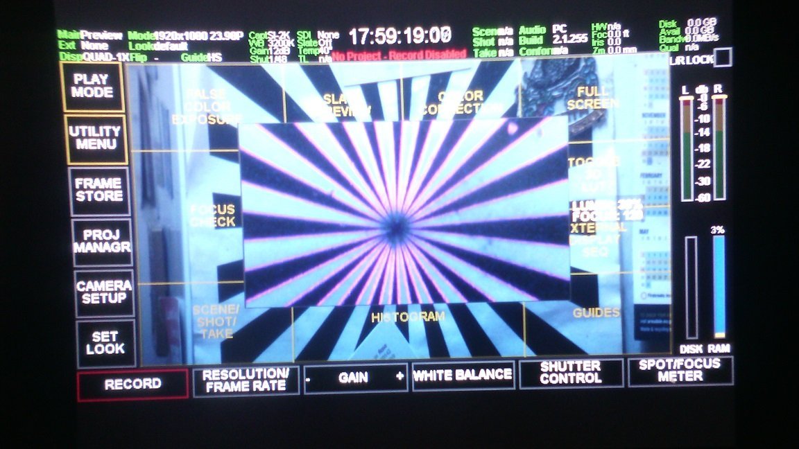
After some headache-inducing concentration firstly chain-drilling two "C" channels then hand-filing them out, I finally got the internal focus trim re-installed on the rear of the adaptor and infinity focus dialled in. Sharpness numbers are comparable via the adaptor as with the NIkon lenses direct to camera in their aperture sweet spot of f4-f5.6. However the sharpness falls away more with the wider apertures.

-
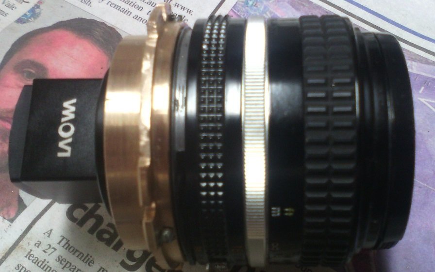
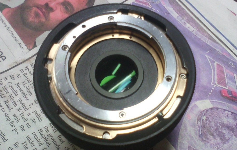
Useless information warning for what follows in this response. For what it is worth knowing. the Laowa 1:33 PL to PL rear anamorphic adaptor can be rebarrelled for PL (rear) to Nikon F-Mount lenses - just, but doable. Why would one do so? If one is an unmoneyed individual with a Nikon F-Mount stills set of lenses, then there is an element of "not because one should not but because one can." It would be possible by use of a custom made extra part to remachine the Laowa genuine barrel but its utility as a PL-PL adaptor would be ruined. I examined adapting the Laowa anamorphic tail for attaching to an EF-Mount or Nikon F-Mount. However this is not easily possible, doable maybe but with interference to the anamorphic adaptor's focus trim adjustment system which would by necessity have to become the EF lens tail. I also examined the possibility of making an EF-Mount to EF-Mount version but there is not enough workspace between the front of the internal anamorphic optical cell and the rear of EF-Mount lenses, a pity because there is only 2.5mm difference between Canon EF-Mount and Nikon F-Mount flanges. Venus Optics' website suggests that mount options other than PL- PL will become available in future. I imagine Venus Optics will choose a different design path to my hacks.
-
What mount is this Angenieux 12-120mm?
Robert Hart replied to Luke Ogden's topic in Lenses & Lens Accessories
If that is a 12-120 Angenieux zoom, then Ken Hale at Whitehouse AV was doing PL-Mount tails for them and the Angeniuex 10-150 as few years ago. If you end up getting hold of one for the Angenieux lenses and fitting it yourself, you may experience difficulty with aperture ring clearance on some lenses. Ken also did a different PL-Mount for the new-old-stock Angeniuex "Compact" zoom lenses left over from the production run of the CP-CSMO cameras. -
Some 16mm lenses in PL-Mount penetrate deeper into the camera throat than some 35mm PL-Mount lenses and may butt against structures within the camera throat behind the mount flange. The BMPCC 6K camera version may have a filter stack which gets in the way of a lens that penetrates further into the camera throat. Some PL-Mount lenses have a deeper shoulder than the PL Mount adaptor mounted in place of an EF-Mount and also butt against structures within a camera throat. They may not play at all with a 0.71x focal reducer (Speedbooster). Please take little heed of my comments and wait for more contributions from others. I am not familiar with the camera types mentioned, only the Optar Illumina / Optika Elite Super16mm lens families and the Cinema Products CP Ultra T* lens family.
-
Creative way to use a busted lens
Robert Hart replied to Vital Butinar's topic in Lenses & Lens Accessories
I have been thinking about getting Rokinons but it seems my all metal old Nikons are something I should stick with. -
Making new Crystal Sync electronics for CP16R
Robert Hart replied to Aapo Lettinen's topic in Cinema Products
Is there a likelyhood that the new control circuitry could fit within the crystasound amplifier enclosure of CP16 cameras with suitable holes drilled for control knob shafts? There may be enough workspace available when the existing amplifier electronics are removed. Is your prototype running off the 20VDC camera battery power or its own source? The CP16R I have in mind is for 24FPS sync. Australia is a long way from you for shipping a heavy beast in these difficult times for reliable shipping. Is there a likelyhood, that the system might become available for skilled end-user fitment, perhaps within the crystasound amplifier enclosure. With no mag striped film available any more, the internal recorders will never again be used. Cheers. -
Diopters for aesthetics not close focus
Robert Hart replied to Pete Raynell's topic in General Discussion
Another spin on the subject of dioptres. Feel free to shoot this messenger, metaphorically of course. There are dioptres and dioptres. The bad ones are a simple single element in a ring which screws into the camera lens filter thread. They sometimes were referred to as "close-up" lenses or "filters". The better ones are known as achromatic dioptres. They have several elements in them. The simple ones do crude cruel things like pinpoints stretched radially/colour separation closer to the edges of the image. The achromatic dioptre images are clean. You might achieve a cool effect with a single element dioptre or maybe even an achromatic dioptre if you mounted it off-axis so that one portion of the image is more out-of-focus and artifacted. I once mounted a fisheye lens off-axis so that the lower portion of the image looked more "normal". You might also degrade its performance by mounting it too far ahead of the camera lens with spacers but not so far ahead as to vignette the image. With a single element dioptre, the colour rendition in the soft area would be rather muddy. -
Roberto. Very valid. I had forgotten to mention that. In a documentary shot in the Pibara region of Western Australia, landscape aerials had to be shot from a Robinson R22 helicopter with a Bolex H16 film camera at its highest frame rate to minimise the shake. It worked very well.
-
Cover the lens glass first with thick wad of tissue or cloth to insulate it. Try some canned air directed onto the lens ring with the little plastic straw with the can turned upside-down so that liquid gas comes out onto the lens ring. This may contract (shink) the metal enough to thermally shock the seized thread loose. Try removing the chilled lens ring before it can warm up again. On another forum it was suggested that a piece of automotive inner tube or other thin sheet rubber on a flat surface may find enough grip on a stuck lens ring to shift it if it is pressed firmly whilst being turned. Be extra careful not to get any liquid gas onto the glass because it WILL shatter from thermal shock.
-
I assume by now you may have made your attempt. I have only just read the post. The available workspace within the Piper aircraft will be very confined especially with a 35mm camera. Shooting through the window transparencies may be chancy if the surfaces are deteriorated by polished-out scratches. Of the small four-seat light aircraft, the most user-friendly is the Maule. A Piper Cherokee Six which has been converted for skydivers may be workable. The Maule aircraft is certified for rear door-off operation which removes the scratched window problem. Your camera needs to be tethered for safety and you would need to be restrained by the existing belts or better, a harness. In the Maule or the Cherokee Six, your direction of view will be slightly rearwards. The Maule has a high wing with two lift struts each side that you have to dodge. An 18mm wide angle lens may pick up parts of the aircraft like wingtips or struts. In this example, I was shooting with a 50mm-500mm zoom lens on a Super16mm SI2K digital cinema camera with a singe Kenyon KS8 gyro. The objects in the image area a cargo rope rigged on the door to stop me from falling out although I was also harnessed and the camera on a lanyard.
-
The colour slashes could be the result of copying from an original distribution which was subjected to an old copyright protection tech which was I think called "Copyguard". I understand there were two processes One diminished the vertical stability to the bare minimum which would apparently defeat some older VHS players when paying legit distribution copies. The other was some sort of trickery applied to the colour information.
-
That problem may be related to a small memory battery leaking onto the motor control circuit board. It ruins the circuits which control motor speed and the park function which then fails to stop the motor even of both run switches are "off". You could enquire with Visual Products and Whitehouse Audiovisual if they have the means to repair. It is sadly the way most CP16Rs die.
-
Variable area tracks look like an audio waveform in a digital edit timeline. Variable density tracks are a constant width with what looks like very fine bars across the full width of the track. Before magnetic audio recording media came along, there were optical audio recorders. Some like Auricon were integrated into the camera itself. Others were separate boxes which rolled film and recorded an optical soundtrack and was used just liike a tape recorder. The optical track was later mated to the final film negative to strike release prints. Synchronisation was achieved by using AC motors in cameras and audio recorders driven by a common source. My understanding was that variable density recording was by using a galvanometer which rocked a mirror instead of a display needle on a gauge, disturbing the direction of a beam of light. There may have been a fine slot aperture and the mirror and light beam may have been larger than the film track itself and scaled to the area of the track using a lens. My understanding of variable area recording is that there was a light emitting device which was similar to the very old visual recording level green displays on old tape recorders. It was some kind of discharge tube. The length of the band of light varied with audio level. Such a display may have been scaled to film track width via lenses and maybe narrowed by a transverse slot aperture to improve higher audio frequency response. Calibrating and setting levels must have been a nightmare but there may have been a live-viewing method for calibrating. Some of the old tech was large and brutally heavy. If anyone has more definite information and can correct my comments, please do so.
-
Canned Air for Sr2, and avoiding hairs!
Robert Hart replied to James Wachtel's topic in Camera Assistant / DIT & Gear
A groundglass viewfinder screen and a fibre-optic viewfinder screen although serving the same purpose are different in their construction. As I comprehend things, the fibre-optic screen may be a coherent glassfibre bundle, a bonded piece sliced thin and dressed smooth as a projection screen like the groundglass. It may be a longer run of fibres arranged to maintain an erect image whichever way a viewfinder eyepiece is oriented. The bundle may be stablised at each end by a transparent adhesive. A similar arrangement is used in tube-based night vision to invert an image instead of a system of lenses. Hit a fibre-optic slice with a high pressure air jet and fibres may disbond causing a blemish in the viewed image. Heed the advice of better qualified people than I. -
Making new Crystal Sync electronics for CP16R
Robert Hart replied to Aapo Lettinen's topic in Cinema Products
Aapo. Regarding a lens for a video split, if your C-Mount camera has a 2/3" sensor, you might be able to use Fujian C-Mount lenses with CS to C-Mount adaptor rings to macrofocus the lenses. The rings are 5mm thick from memory. The Fujian lenses are available as 25mm, 35mm and 50mm focal lengths. I was examining this at one time. My notion was to cut an approxiately 5mm thick piece of aluminium in the shape of the little hatch which closed the hole for the video split, mount it in a 4 jaw chuck on a lathe then machine the thickness down to leave a hollow shoulder to cut a thread onto for the filter thread of the lens as a means to mount it then use the lens to support the camera. https://www.ebay.com/sch/i.html?_from=R40&_trksid=p2334524.m570.l1313&_nkw=fujian+C-mount+lens&_sacat=0&LH_TitleDesc=0&_odkw=Fujian+50mm+c-Mount+lens&_osacat=0 -
Making new Crystal Sync electronics for CP16R
Robert Hart replied to Aapo Lettinen's topic in Cinema Products
Aapo. How difficult would it be to design a simple single-speed crystal-controller for the CP16R with the shutter park function. Multiple speeds are nice but maybe not necessary. Offspeed work is easily done on a Bolex. High speed shooting for slow motion is more conveniently doable with digital cinema and at less media storage cost than 16mm film. -
Canned Air for Sr2, and avoiding hairs!
Robert Hart replied to James Wachtel's topic in Camera Assistant / DIT & Gear
If a slug of liquid gas comes out because of shaking the can from habit or turning it upside-down which you should not, shock-cooling of any optical glass the gas hits may crack it. -
Are regular 16mm cameras worth investing in?
Robert Hart replied to Brett Allbritton's topic in 16mm
Appo Lettinen. How is it progressing? Will your final CP16R system be contained within the camera body. I think I saw a post somewhere that suggested you were thinking about a box outside of the camera. A tidier solution might be to take out pre-amp and amplifier board out of the Crystasound amplifier attached on the right of the RA models and put the extra electronics in there. -
Angenieux 10-150 remount possibilities
Robert Hart replied to Jay Young's topic in Lenses & Lens Accessories
Ken Hale of Whitehouse Audiovisual remounted in stainless steel, the Angenieux 10-150mm zoom. I have one. With some examples of the lenses, there may be difficulty with interference to the aperture control ring. I bought the PL-Mount from Ken and fitted it myself in Australia. I would not recommend this route unless you have some serious fine mechanical skills for you will ruin something otherwise. -
I can't speak for the Vinten 20 but I have had a roam around inside a Vinten 22. The Vintens have some tricky ways of coming apart. Pulling one apart is not for the fainthearted. You are dealing with some fine precision in some parts. The counterbalance spring mechanism can also be damaged if dismantled incorrectly. The friction material is also proprietary and expensive. So far as I know, if you can obtain it at all, it will be in bulk amounts far more than you would need. The fixed "labyrinths" ( my translation is non-adjustable friction modules ) establish an initial level of friction. They are apparently filled by a vacuum process on models since the SDs. There are extremely fine clearances in the labyrinths and parts are matched in the factory to achieve this. I understand that they are not serviceable but replaced as an assembly. I have taken one labyrinth apart and found that material had squeezed out. There had been a metal-to-metal contact between two aluminium surfaces. They had galled raised patches which snagged lightly as they passed in the tilt motion. People tend to misunderstand what Vintens do differently to other products. They mismanage Vintens and overtighten the friction adjustments as tilt and pan locks instead of using the tilt and pan lock levers. This eventually ruins the adjustable friction. If friction material has become entirely extruded, the catching you describe may be a metal to metal grab happening in an adjustable friction module. These consist of a machined aluminium face and a polished stainless steel face with the friction material in between. The draw motion is mechanically limited. Frustrated users who expect the adjustable friction to increase to lockup, overtighten the adjustment knobs which reach limit stops. The next step is they reset the limit of the knobs to achieve more tightness and eventually break linkages or strip draw threads. If the snatching you experience if happening in the tilt motion, you might be able to correct it by backing off the adjustable friction, storing the head in a warm place on its side with the tilt controls lowest for a few days, then exercising the full tilt motion with the adjustable friction backed off in the hope of distributing friction material evenly across the surfaces. If you are getting snatches with the pan friction you ight be able to restore it by storing the head camera-side down in a warm place with the friction adjustment backed off and exercising as for the tilt motion after a few days. The pan friction adjustment if overtightened will break out a small machining in a bellcrank which holds a hinge pin on the end of a draw rod. Once that breaks, the draw rod will come out some way with the knob and that part of the head will have become ruined.
-
Some otherwise identical lenses of which some are parfocal and some are not may depend on whether they were coillimated for a camera which shot striped film, the stripes being magnetic tracks. There were two tracks, one being the sound recording media and the other a narrow strip called the "balance track" which ensured the film rested flat in the gate. These tracks set the film emulsion very slightly rearwards. Bare film used in a camera with a lens or camera mount collimated for striped film may rest very slightly forward of the image plane of the lens. The image plane of a lens collimated for a striped film may in a digital cam rest sllghtly rearwards of the sensor plane. Whilst you can focus must fine with a live view digital camera screen, the zoom movement may no longer be parfocal if this condition exists. Thinner shims may be needed between the mount tail of the lens and the lens body. Shimming and collimating lenses and camera mounts to a common standard is a dark art best left to the skilled artisans who do it for a living.