


Robert Hart
-
Posts
399 -
Joined
-
Last visited
Everything posted by Robert Hart
-
There may be a tight take-up clutch bogging the motor down as the roll gains diameter and more leverage against the motor and the outgoing roll loses diameter and is harder for the motor to drag film from. I don't know what system your camera has but there may be some form of friction clutch with an adjustable compression spring. In the CP16, the take-up drive had to be set just right or the film would wind loose or if too tight, the cogbelt might become damaged if it was deteriorating.
-
Making new Crystal Sync electronics for CP16R
Robert Hart replied to Aapo Lettinen's topic in Cinema Products
If you are going to remove that control board, please don't throw it out. I may beg you for it. I have a camera which developed a runaway problem. It would go off speed and then would not switch off. The battery had corroded the PCB but the traces are still there. Is the failure the ICs being fried by stray voltages travelling through the blue corrosion soap from the main battery? I originally bought the camera as a parts donor for another but it turned out to be a bowtie shutter model not the last BBC version which is also worn. It was initially a goer and the main spindle bearing is not worn like the older non-reflex CP16 newscamera I first bought. That camera has worked long and hard. It has a notched claw from wear. The control board in the non-reflex camera does not appear to have a memory battery and it does not have the park after stop feature or speeds other than 25FPS ( for PAL TV ). There are no special Cinema Products-branded ICs, only RCA-branded of three product numbers. -
Soldiers of the Cross probably deserves a first in there somewhere. https://www.imdb.com/title/tt0000335/
-
Long Exposure / How to you get this effect??
Robert Hart replied to raphaelle gosse's topic in Visual Effects Cinematography
So long as there is little motion in the image, stacking layers of the same clip in your editor successively one frame delayed with transparency over a firm base image track confers a noise reduction effect. It also paradoxically enables passing objects like cars at night in street lighting to be "seen" through light hedge foliage when you pan with the vehicle. It is useless information in these times of affordable effective noise reduction but a workaround back in the times when Adobe After Effects was hell expensive. -
Slightly offtopic but related. Due to mishap, some archived early generation videotape British TV shows in colour were lost. Some time back, old B/W filmed distribution copies were discovered in an African TV broadcast station, in Nigeria I think. In playing them via modern telecine, it was discovered that traces of colour were appearing. Apparently the resolution of the film was just sufficient to have also captured the unique moire pattern of a PAL colour TV image which carries the colour information. With some R and D effort and the power of modern digital technology, it was apparently possible to recover in colour, the original coloured versions of the shows.
-
Making new Crystal Sync electronics for CP16R
Robert Hart replied to Aapo Lettinen's topic in Cinema Products
Further to the above response, here is a link to an older discussion on the other replacement controller project. -
Making new Crystal Sync electronics for CP16R
Robert Hart replied to Aapo Lettinen's topic in Cinema Products
A few years ago, a guy in the US developed a modern electronic replacement for the motor controller system and also a replacement operator panel for the rear. They were to be marketed but it seems the project faded. The memory battery for the footage counter is the nemesis of the CP16R electronics. The battery leaks. Chemical gets into the crystal unit and also erodes the tracks on the PCB. Take care that the little teeth from a damaged belt do not get into any of the gears. -
I doubt you will achieve the perfect optical result with the B4-Mount lens on a CP16R but it will not be too bad at apertures of about T4-T8. The B4-Mount lenses are set up so that three 3 CCD sensors see the lens image through a prism. In adaptors for B4-Mount lenses to single CMOS sensor cameras, there is a thick planar optical glass element in the adaptor. This element projects too far rearwards to clear the mirror in the CP16R throat for both the Blackmagic B4 adaptor and P;+S Technink IMS B4 adaptor. The "in air" flange to focal plane distance for the B4-Mount is 48mm. For the CP16R is it 38.1mm according to another response here. You will have insufficient workspace for the waist for the CP-Mount clamp ring clearance of at least 6.4mm forwards of CP-Mount flange face plus the at least 5mm plus for the clamp ring of the B4-Mount rearwards of B4-Mount flange. That 11.4mm plus, uses up your available 9.9mm of workspace by about 2.5mm of interference. You might think you are able to share a total of 2.5mm to be shaved off the rear of the B4-mount clamp ring and the front of the CP-Mount clamp ring except that the CP-Mount clamp ring is a two-layered construction. You will destroy its integrity by shaving anything off it. That leaves more to be shaved off the rear of the B4-Mount clamp ring and you do not have enough meat on the threaded section to be assured of sufficient strong thread engagement. So the adaptor route is done for, cactus, futile, dead-ended, unless all other moving components are remade - maybe?? Your choices therefore are to make a new CP-Mount tail for the B4-Mount lens or make an entire B4-Mount to replace the CP-Mount on the camera. Making a new CP-Mount tail for the B4-Mount lens will be simpler. You might be able to shortcut the process a little by using a salvaged B4-Mount tail off a scrapped lens, longer screws for the tail and a thick spacer between the two. The profile of the two mount systems is very similar with probably about 0.5mm in diameter difference for the wings on the tail outer and inner. However, the CP-Mount inner shoulder rearward of the flange face is considerably wider which would require a ring adaptor on the B4 tail shoulder. There is also a shroud overhang on the B4 tail which will interfere with the spinning mirror of the CP camera. You would also have to relocate the pin in the B4 tail to engage with the slot in the CP-Mount. Good luck with your endeavours.
-
Canned air with a plastic straw with the can held upside/down so that liquid gas comes out and freezes what it touches is a desperate measure. Keep it away from lenses and mirrors because it WILL crack them due to thermal shock. Dew also forms which may not be good.
-
Manual focusing - digital screen vs groundglass
Robert Hart replied to Jon O'Brien's topic in Camera Operating & Gear
It can sometimes be helpful if you have a sound guy swinging a boom pole, to mount a laminated paper focus star on the pole near the mic and focus on that just before the boom guy and you are checking the frame edge. -
Operating Whip Pans or Quick Landing Shots
Robert Hart replied to Nelson JJ Flores's topic in Camera Operating & Gear
Some tripod heads allow you to mount a second pan-handle on the left facing forward. I use this technique not for filmed drama but for chasing agile aircraft in flight. -
Years ago in Australia, a poorman's shoulder stabiliser was innovated. It was a two man system. The shoulder mount had an extension rearwards about the length of a broomhandle with a wide teebar on the end. The second operator walked behind the first and kept the camera horizontal by his grip on the teebar. I think they had to choreograph their steps and coordinate their planned move a bit.
-
What are some good but obscure VHS tapes that need archiving?
Robert Hart replied to Daniel D. Teoli Jr.'s topic in Off Topic
One which seems to have disappeared is "Prisoner Of Rio". It was interesting because the subject of the film, Great Train Robber Ronnie Biggs actually was cast in the film but not as himself. -
How was film put on VHS back in the day?
Robert Hart replied to Daniel D. Teoli Jr.'s topic in Post Production
Towards the end of VHS distribution the imaging started to look better to me, maybe due to mastering which met DVD and BluRay standards. -
It is likely you have a short loop. The linked clip is not the be all and end all of how to manage the CP16R but the methods worked for me. There are also some other clips on managing the CP16. After film has been loaded in the CP16 for a while, the upper loop bend and the tight bends around the drive sprocket rollers and the infeed roller become shape-memorised by the film. The signature starting sound of the CP16 may be a smooth run for half a second, then a soft momentary clatter, then two soft momentary clatters and sometimes rarely a third as shape-memory bends momentarily lift the pressure plate which chatters as the claw pulls the film through. If the clattering is continuous, you need to reform the loop. You should only experience this if the film has been in the camera for a long period and even then very rarely. The lower loop on its progression should be almost brushing the black felt acoustic insulation in the bottom of the camera body and barely touching the fixed guide stud below the gate for the loop to be correct. Enjoy your camera. Properly set up and maintained, despite all manner of rumours and folklore to the contrary, the CP16 film transport will pass a double-exposure test as well as a pin-registered 16mm camera.
-
The screw may have been replaced if an original fell out and was lost. Does your lens's screw have a narrower smooth toe with no threads on its end. It may be that the screw is screwing in but the threads may be interfering with the sides of the squarecut channel and stopping it from sliding back and forth past the screw. If the screw is too long, it may be bottoming out in the squarecut channel and jamming the optical block against the barrel on the opposite side.
-
DETACHED BLUE SENSOR JVC GY-HD100 AND OTHERS OF THE ProHD FAMILY
Robert Hart replied to Robert Hart's topic in JVC HD
This clip is of a test alignment of the blue sensor in its temporary bridge pieces. You'll have to be quick to spot it just after the title. There remains a need for a rotatational adjustment the sensor. -
DETACHED BLUE SENSOR JVC GY-HD100 AND OTHERS OF THE ProHD FAMILY
Robert Hart replied to Robert Hart's topic in JVC HD
Obviously much finer alignment is needed. The blue margin is a result of the sensor not being quite flat on the prism surface in the lower right corner.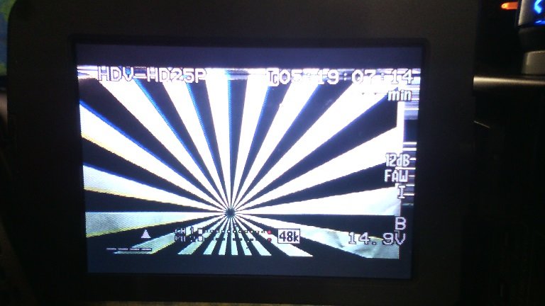
-
DETACHED BLUE SENSOR JVC GY-HD100 AND OTHERS OF THE ProHD FAMILY
Robert Hart replied to Robert Hart's topic in JVC HD
A small update.Here is an illustration of a temporary support for the detached sensor which enabled me to establish just where in space it should be. The next step is to build a different support attaching to two pairs of screws and is microadjustable and yet enables enough clearance that the small dobs of adhesive can be spotted upon the four corners of the sensor to prism junction.The material needs to be viscous so that it does not creep or wick in between the sensor and the prism through capillary action.The adhesive appears to be a non-brittle material similar to white water cleanup bathroom sealer.The bridgepiece is cut from formica or laminex which is a material similar to thermosetting resin or bakelite. It is insulative to avoid any chance of electromagnetic fields being introduced into the original steel jig pieces which function also as heatsinks. EMF seems to have been an issue because magnetic strips have been taped to the ribbon cables.The bridgepieces block airflow so cannot be a permanent solution.The far bridgepiece has been made to be a precise fit to another intact sensor block with three screws. There are elbows in the far jig pieces which have threaded holes which are conveniently are a match to the camera body screws. This cannot be an accurate exemplar because each sensor itself is very slightly different and must be aligned before the adhesive is applied in factory. It does however get very close. The bridgepieces are cut to be a very slight interference fit to the jig pieces.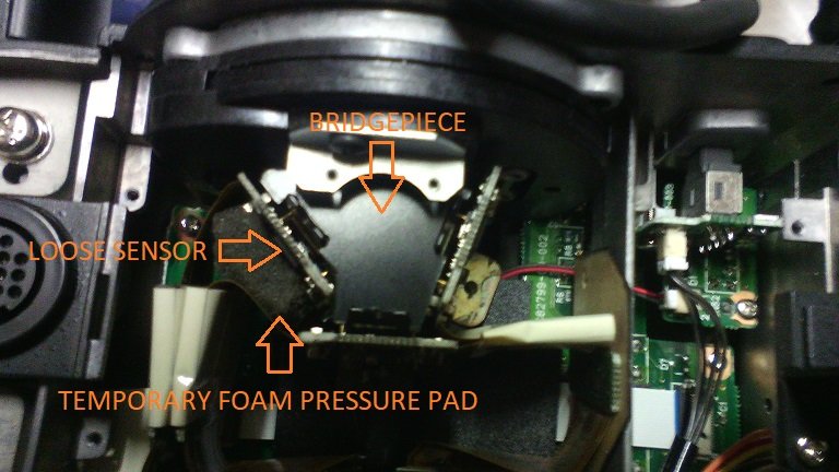
-
DETACHED BLUE SENSOR JVC GY-HD100 AND OTHERS OF THE ProHD FAMILY
Robert Hart replied to Robert Hart's topic in JVC HD
For those who have the endurance to remain curious, any bridge pieces which are made have to be vented to allow the small fan to push air through. As Tyler has mentioned above, the little processors on the PCBs the sensor chips are mounted to can get hot enough almost immediately to be on the pain threshold. The bridge pieces are best made of formica or laminex sheet which is a thin thermosetting resin similar to bakelite. I have established with these it is possible to get a good alignment but perfection will only come from screw adjustments, not finger pressure and barely tightened screws. Once I have established a position for the loose sensor I will make up different mounts attached to four conveniently located screws on the rear face of the mount to confirm to the restored position of the sens and use that instead of bridging all the sensors together. -
If they really have a passion and commitment to this project and are not doing the entitled thing, they will find a way to make the financing happen or find a patron. That patron should not be you unless it pleases you to sponsor the project for the feelgood or "the exposure". When it comes to loyalty down the track from up and comers, you can pretty much assume it will be non-existent if they step on the fast train. Those who hire a new director are not likely to want any attachments which come with him or her.
-
DETACHED BLUE SENSOR JVC GY-HD100 AND OTHERS OF THE ProHD FAMILY
Robert Hart replied to Robert Hart's topic in JVC HD
It seems that it can be done. This phone pic of the LCD screen is of the image from a JVC GY-HD111E with detached blue sensor relocated using rough cardboard bridges made from cereal packet cut with razor blades. Obviously the adjustments would have to be finer before the image on a large display screen would hold up but this is a good start. What a pity I did not do this a few years ago. I might have made a few dollars. Now I am just patching up museum pieces and there is no worth in it.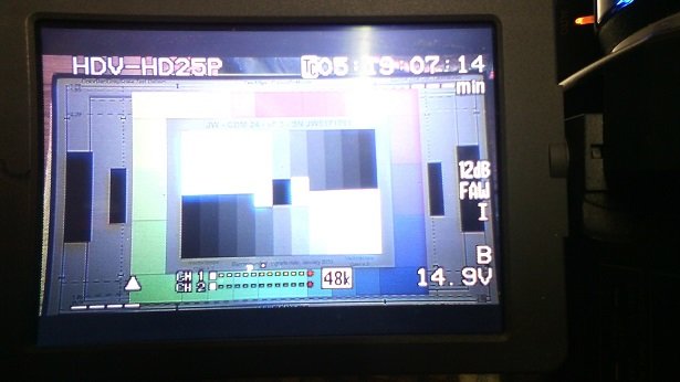
-
DETACHED BLUE SENSOR JVC GY-HD100 AND OTHERS OF THE ProHD FAMILY
Robert Hart replied to Robert Hart's topic in JVC HD
Tyler. There is a little fan in there but the blue sensor is highest in the group and probably receives more heat due to convection. There is another dynamic in play with the blue sensor in that the ribbon cable is only just long enough and imparts a lot of constant draw tension on the blue sensor board. Over time I suspect this has been the mechanism for the sensor coming off. This can be converted into a pressure load by adding a spacer between the upper surface of the blue channel ribbon cable and the underside of the SD card slot assembly above. Whilst doing a "live test" with the blue sensor bridged on one side to the other sensors and manually adjusting the free edge, I observed that the green sensor, whilst apparently firmly attached can flex very slightly on the adhesive and spring back. I did not try the red sensor. Sleeping dogs are best left to lie undisturbed. When playing around inside a camera with a loose blue sensor with the right casework removed, take care to insulate between the edge of the blue sensor and the green sensor below it. They will short to each other and the camera will go dark. I thought I had destroyed it but it seems that this crashed whatever computer is inside it. When switched off and switched back on again it was fine so I dodged the bullet that time. Phil. The blue sensor coming off, creating a yellowish hue which won't whitebalance out has been a common failure mode with the JVC GY-HD*** camera family. Another failure I have with one of the three cameras I have here which has an intact sensor block is that half of the green channel has faulted leaving a purplish hue on one side. The fault is in the sensor and its downstream connector. The fault carries over to another camera when the block is installed in it. That sensor block is my template for making the bridge pieces. Each sensor block will be individually slightly different because of manufacturing differences between sensors when the imaging chip is first installed. I am hopeful that the differences are so miniscule that simple tapered screw adjustments will enable the pixel rows to line up. The system was accurate enough to enable fine flying head adjustments on the old Sony EIAJ reel to reel video recorders. Shimming was another matter. The adhesive seems to be similar to the water washable white bathroom sealer and is not dead hard but slightly pliant. It cleaned off from both the sensor face and the prism glass like bathroom sealer with a small wooden blade, a cut-down icecream stick. I don't like my chances but I have sent a request to JVC in the US asking what they used for adhesive. It appears that there are only four small points on the corners where there is adhesive in spots of about 1mm at most. -
This has been a common failure in this camera family usually manifest firstly with blue rimming on hard contrast edges, becoming a soft and separate ghost blue image or no blue image at all, just a blue moon shape and a yellow cast in the rest of the image which users cannot white-balance. The fix from JVC is to replace the entire sensor block at considerable expense which given the obsolescence of these cameras is not justified. Because of the manufacturing technique and the attachment of the sensors to the prism by adhesive alone with no other mechanical support, alignment of the detached sensor and reglueing it is not an option. However a means of attaching the blue sensor using two bridgepieces from the green and red sensors attached to jig hardware which remains on the individual sensors may be an option. From rough tests it sees doable, the issue being finding space to add small adjustment screws.
-
Age becomes an issue when there are many kid eagers out there prepared to provide their brand new camera and work for monkey-tucker. Good luck to them with their energy and their ambition. In the meantime once a succession of them have worn themselves and their cameras out subsidising an exploitative industry and a production entity eventually gets burned by a reshoot, us wrinklies will have gone on the dole queue.
